Saturday, January 30, 2016

Pin Holga

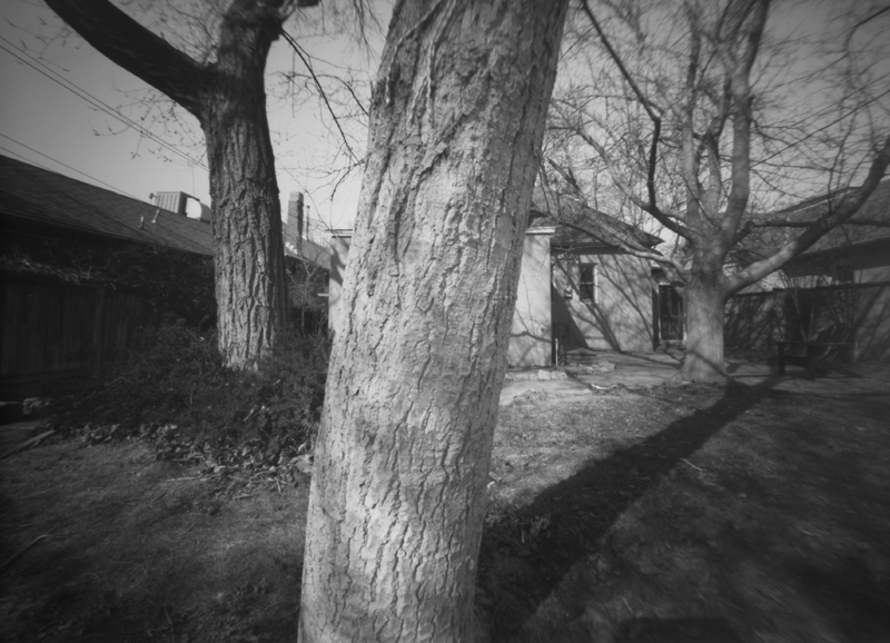
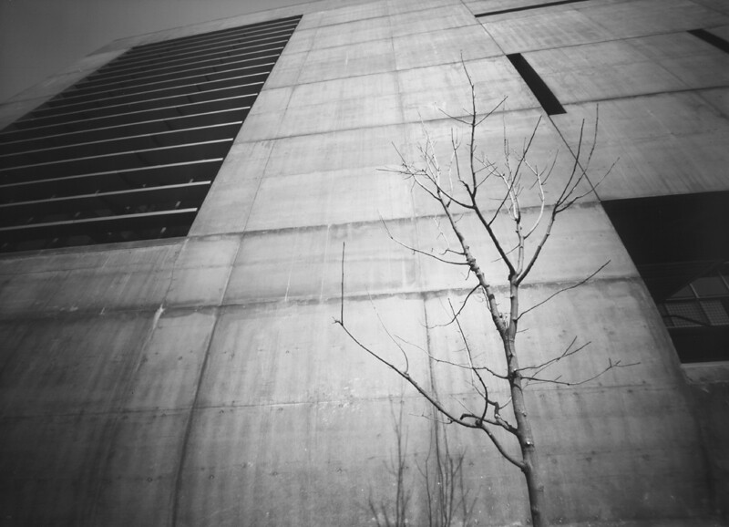
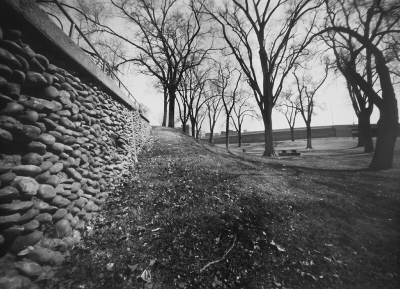
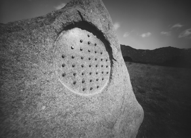
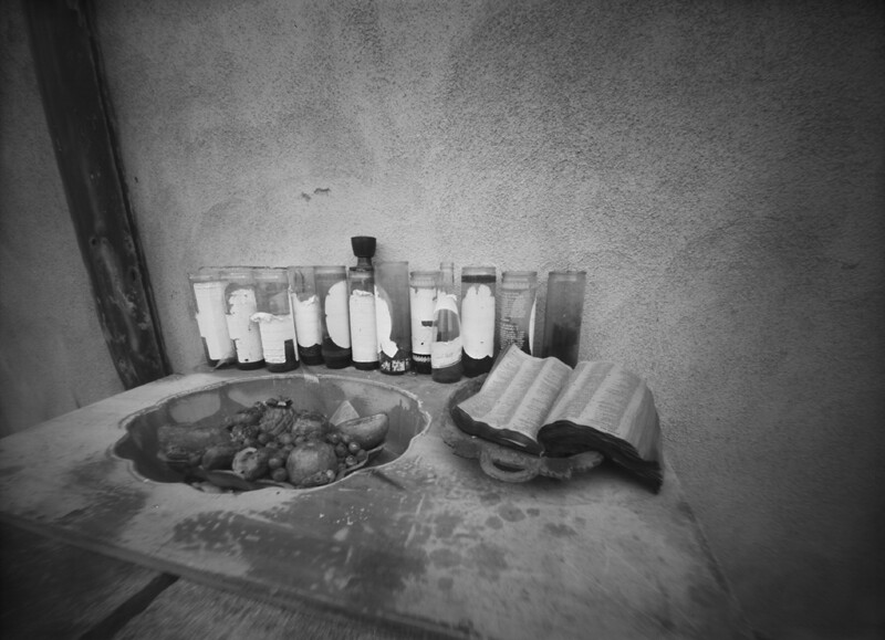
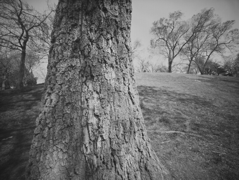
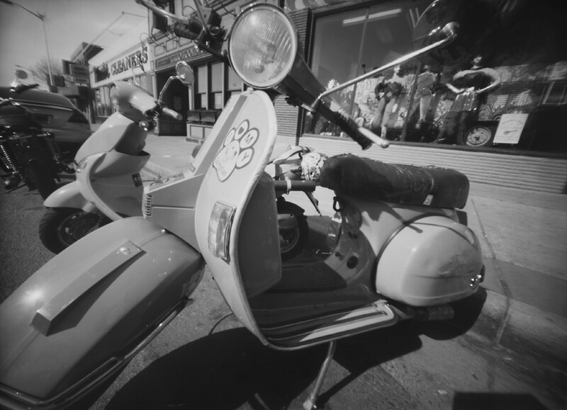
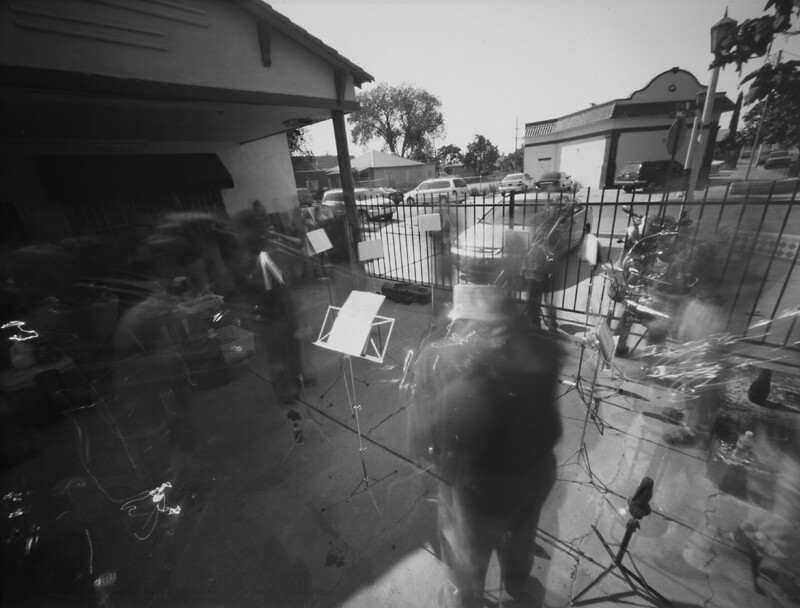
Two001a
Fuji Acros 120, printed onto Ilford MG RC WT paper

I don't always create pinhole images with handmade cameras and photo paper, though most of my pinhole history has involved doing just that. But there was a time, a few years ago, when my curiosity got the better of me and I plunked down money for a commercially-made pinhole camera, Holga's 120-format Pin Holga.

It seems natural that Holga would have eventually released a pinhole version of their ubiquitous plastic camera, since they already had the bulb-mode necessary for the lengthy exposures required of pinhole cameras. However, what I found necessary to make the camera a bit more practical was purchase of the optional shutter release cable accessory, a plastic bracket that clamps around the lens housing and positions a threaded metal insert directly above the camera's plastic shutter button; without this accessory you'll find yourself having to hold down the shutter button for the duration of the exposure, introducing unnecessary motion blur to the image.

As for the quality of the pinhole itself, I found it to be a reasonable compromise between sharpness and practically short exposure times. The biggest issue for me is that the position of the pinhole, in what would be the camera's lens mount, precludes it from offering a truly wide angle of view, and thus the resulting images lack that corner vignetting so common with their other cameras. I suspect this was made necessary by them having to use their standard leaf shutter mechanism from the lens cameras, whose position is simply too far forward to permit wide angles of view.

I would assume that a resourceful person, needing a wider angle of view, could hack a Holga with a simple lens cap shutter, dispensing with the lens housing and leaf shutter protruding from the front of the camera body altogether, and mount the pinhole inside the camera body closer to the film plane.

I found the Pin Holga simple and practical to use, with its tripod bushing, reasonably modern film advancement mechanism, window-style viewfinder and shutter release bracket in place. One modification I did make (Holgas seem to invite customized improvements) was the application of some hook-and-loop tape around the rear door area, to prevent the flimsy clips, that serve as both door locks and strap lugs, from moving and risking the door falling off with a roll of film inside. I also have a piece of tape over the film counter window, as a just-in-case measure against light leaks; because you just never know.

While I do enjoy the lightweight, compact size of the Pin Holga, something about it just doesn't draw me to using it all that often; perhaps it's because of its more narrow angle of view, or the cost of medium format film and processing, or having to, in the case of black & white film, print each frame individually in my darkroom. Yes, the convenience of Harman's Direct Positive Paper has spoiled me, somewhat.

In comparison, using the 2" square-format brass plate camera, discussed in the last article, seemed much more enjoyable, and the results more pleasing.

I suspect that part of the reason is because, for me, working with various paper media is more enjoyable and convenient, the results easier to scan than film. And I've been working with paper negatives for several decades (and more recently Harman DPP) and have become more accustomed to the process.

One thing I have done (not with the Pin Holga but with lensed Holgas), demonstrated in one of my You Tube videos, is to load individual sheets of the Harman paper, via my darkroom, and use the bulb shutter to make timed exposures; perhaps I should break out the Pin Holga once again and try that out.

Sunday, January 24, 2016

The Rediscovery of New Beginnings

P1110608a
It might seem almost a cliché to say this, but sometimes one has to lose something in order to gain something else. Or, to paraphrase another adage, out of loss comes new beginnings.

No, I'm not referring to some personal tragedy; I've lived a rather sedate life, if truth be told. No, this has more to do with the idea of lost opportunity, of the promise of unlimited creativity squashed by life's inertia, perhaps.

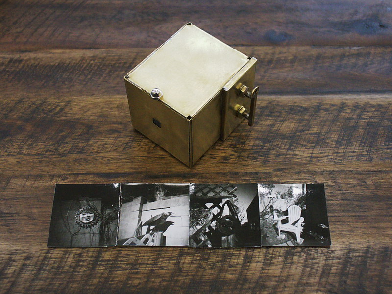
Some time ago I had created a video for my You Tube channel, within which I made mention of, and demonstrated, a small, brass pinhole box camera, designed to make small images onto two inch square pieces of photo paper or film, taped to little brass film plates that fit into the camera via a changing bag. A humble little camera, it had seen much use about a decade ago, and promised much more, but since then has been relegated to the storage bin, acquiring the patina of disuse. Alas, such is life, so full of opportunities missed or squandered.

But then something curious happened. One of my video's viewers had recently contacted me, inquiring about possibly purchasing a copy of said camera. Thinking it over for a day or two, I finally decided that, rather than try to recreate a one-off camera design, why not just sell this very same camera? After all, it wasn't getting much use any more, being stowed away for all of these years, its last use only a distant memory in the back of my mind. I had recently been thinking about what to do with this sizable collection of pinhole cameras I've assembled over the years, that are no longer getting regular use, thinking of perhaps giving them away to some local school's darkroom program, if they'd have them, but never made any progress on the idea. In this newfound opportunity, I sensed that perhaps something better could come of it than what I would ever have accomplished on my own; the person wanting to buy it is a graduate photography student and aspiring artist, and so I am flattered to see this little gem of handiwork get a second lease on life in the hands of someone much more creative than myself.

But first I had to clean up the camera a bit, it being spotted and blotched from years of misuse; a thorough cleaning would prepare the brass surfaces for growing a fresh new patina, representing a true second lease on life. But also, I wanted to test out the camera a bit, to make certain that it indeed still worked as advertised, and also for the opportunity to include a few sample images along with the camera when I shipped it; I had never before used it with Harman Direct Positive Paper, and was anxious to try it out. I also wanted to experience working with it one last time.

In deciding to make these test images using the Harman paper, I was reminded that normally I wouldn't use this paper in a pinhole camera, due to its extremely slow speed in cameras whose focal-ratios might be well into the hundreds, which in my past experience has required extended exposure times, even in bright sun, of well over a minute or two. But this little camera has a focal ratio of only F/140, sufficiently fast to permit an exposure time of only 15 seconds or so in bright winter's daylight.

The resulting prints startled me in their quality, I must admit. No, I don't really have seller's remorse; I'm happy to see this camera go to a better home, where it will, at long last, see its purpose in life fulfilled. But in the process of letting go of it, I had gleaned a newfound appreciation for how beautiful a small, well-crafted direct positive pinhole print can be. These images are small, certainly, but also sharp - startlingly so; enough so that one would be hard pressed to tell that they had been exposed in a pinhole camera at all.

This last week I've been preparing the camera for shipment to its new owner, including making a wooden base upon which the camera can be mounted securely to a tripod, and through this process I began thinking deeper about these pristine little prints produced by this humble brass box, thinking that perhaps I need to dig out of the storage bin another small-format pinhole camera (or, dare I say it, make yet another?) and try my hand again at more of these diminutive direct positive prints. There's something intimate and personally familiar about these small, 2" square images; they don't cry out for attention with some ostentatious artistic pretension, like mural-sized prints in today's photographic galleries might; they're smaller than what one might view on one's own smartphone, even. You hold them in your hand, nestled in your palm ever so delicately, like a dried leaf or dead insect, and peer into them in wonder, like artefacts of some lost archaic process, up front and held close to one's self. They're small enough that you have to expend some effort in comprehension, but not so small that you need a magnifying glass.

I can see displaying these little prints matted to an oversized frame maybe eight or ten inches square, big enough to isolate them from their surroundings, to give each one the space they might need to breathe their own life and find their own context, with the help of the viewer's participation.

By the end of this week, this little camera will be forever out of my hands, hopefully in better charge of someone more intent on photographic creation than I; but what I've gained in exchange is a newfound appreciation for the power of small, pristine quality pinhole prints, and for that I'm grateful, considering myself richer for it.

A technical side note might be in order, pertaining to how I develop these little prints. Yes, one could easily do so in open trays in one's darkroom. But my darkroom these days is chilled by winter's cold, being located in an unheated garage, and so I prefer the convenience of using a developing tank in the comfort of my warm kitchen.

Those of you who've seen my You Tube videos might know how I do this, but for these small prints it involves taking a small metal 35mm developing tank and adapting it for use as a makeshift rotary processor. For one or two prints, I will keep the metal reels inside the tank and insert the paper, emulsion side facing inward, in the gap between the outer edge of the reels and the inside surface of the tank. Two such prints can be thus positioned, opposite each other so any potential movement won't cause them to overlap and interfere with their processing.

For three or four prints at once, I will remove the reels and apply little loops of painter's masking tape to the inner side wall of the tank, which will hold the prints into position, evenly spaced for processing.

Only 110 milliliters of chemistry are required for processing; I will typically use Ilford Multigrade or PQ paper developer concentrate, diluted "1+10," meaning 10mL of concentrate into 100mL of water. Once the prints are mounted in the tank and the lid installed (requiring a changing bag or darkroom), the chemistry is poured in through the lid of the tank, which is then positioned on its side and gently but continuously rotated for the duration of the processing time. This particular volume of chemistry is more than adequate to process four prints at once, while being insufficient to cause the liquid to slosh out of the lid while being oriented sideways and rotated. In a rotary process, instead of the tank being completely filled with chemistry, as you would with roll film, you only need this small volume, enough to just periodically submerge the paper as the tank is continuously rotated.

It helps to have a roller base upon which to spin the tank; while automated systems can cost thousands of dollars, and you can purchase a manual Jobo roller base for upwards of $50 or more, it's possible to make such a manually-operated base yourself, using parts readily available from the hardware store, which I'll cover in a subsequent article and/or video. But even without a roller base, you can simply lay the tank on its side and slowly rotate it on your kitchen countertop; use a cutting board or other thin piece to elevate the body of the tank far enough above the work surface so that the lid of the tank overhangs the edge of the board, with the opening pointed over the edge of the sink in case of spills, permitting it to rotate easily, while remaining level. Also, a terry cloth or similar dish rag on the cutting board can often help the tank rotate easier.

I have three such stainless developing tanks, and have noticed that two of them leak slightly from the edge of the lid when placed on their sides and rotated, and so I only use the third tank as my dedicated mini-rotary processor; if yours leaks, just take the necessary precautions.

I should mention, when working with fiber-based print paper such as Harman Direct Positive, of the need to adequately rinse the paper after processing, in order for it to be considered archival; otherwise the fixer chemicals will remain within the paper fibers and, over time, degrade the paper; because of their plastic coating, RC papers have less of an issue with this, but Harman Direct Positive only comes in a fiber paper version. For this reason it is advisable to use a rinse aid after the fixer and initial rinse, to help shorten this required archival rinsing time and conserve water.

After the final rinse, the paper needs to be squeegeed off so its front and back surfaces are just damp, then use a hair dryer to dry those surfaces; the inner paper will still be wet, however, and thus the paper will need to be thoroughly dried. When doing so, fiber-based paper has a tendency to severely curl toward the front side of the paper, due to emulsion shrinkage. To prevent such curl I will, after squeegeeing and blow drying, tape the prints face-up to a sheet of glass, using drafting or artists tape along the very edges, then place it in a warm, clean area for several hours. Periodically check on the paper and, if needed, reattach the tape if it starts to peel up from the glass due to the paper's curling. If done properly, you can get fiber prints to dry very flat using this method, without the added expense and bulk of a dedicated print drying machine. Making do and improvising is the secret to success with these legacy processes.

It's difficult to adequately describe the joy I experience when I open up the developing tank after one of these short 10-minute processing sessions and behold these pristine little gems still wet in my hand. It's something about their diminutive size and unexpectedly sharp appearance that gets me every time. I invite you to experience the joy of pinhole photography for yourself, the rediscovery of new beginnings.
Sunday, January 17, 2016

Photo Storage Box Pinhole Cameras


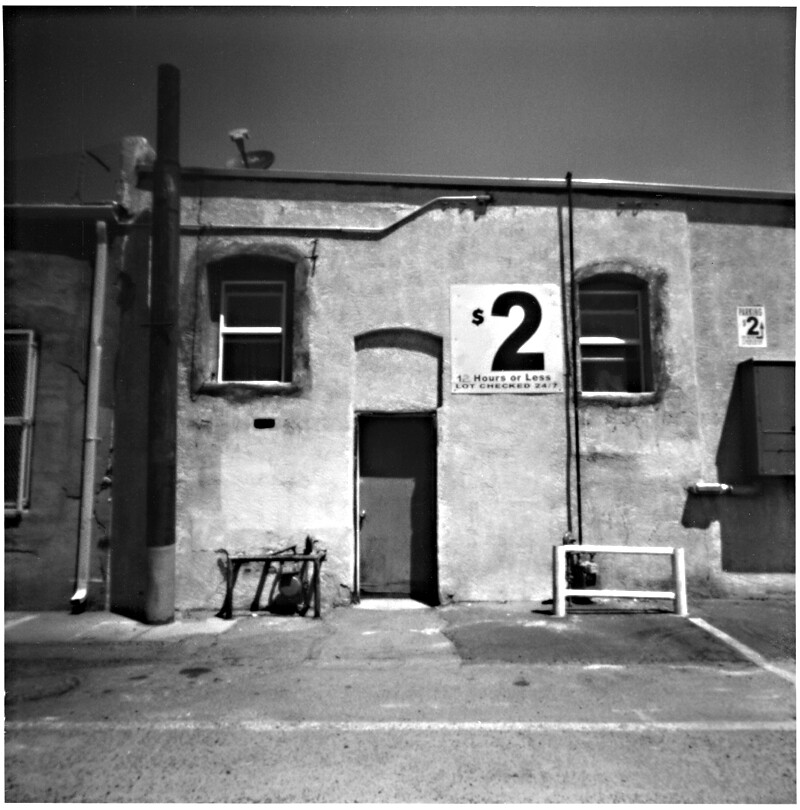
I've covered in past articles a number of different box camera designs, and today I'd like to discuss making pinhole cameras from photo storage boxes. As background, there are times when I've built pinhole cameras entirely from scratch, while other times I will notice a box or container in a store with some feature that presents itself as being a likely candidate for conversion into a pinhole camera.
Craft stores are a likely place to find such boxes, and one of the most common and least expensive are these cardboard storage boxes for photos and videos. These come in a variety of colors and surface finishes, but the ones that initially piqued my interest were finished in black felt, including along the inside edge of the lid, implying that they came already light-tight.

Some years ago, out of curiosity, I purchased one of these boxes in order to experiment with it, with the thinking that if it didn't work out as a camera then I could always use it for its original intended purpose, as storage. The first thing I noticed was that, although on its long side it could fit an 8" x 10" sheet of photo paper, it was too narrow on its short side; unless the paper were curved to fit, or trimmed to size.

Once converted to a camera, I initially made some test shots with the paper mounted curved inside the box, but movement of the paper while the camera was pointed downward caused some of the corners to be blurry, and so I subsequently converted it to hold the sheet of paper, trimmed to fit, instead flat against the inside of the box, using a cardboard holder piece, with gaffer tape handles for easy removal.

While deciding how to convert the box to a camera, I had to decide how best to orient the paper relative to the lid. While it might be easier to insert and remove photo paper into the shallow lid of the box, having the film located there would mean a higher chance of it being fogged by light-leaks from the nearby lid opening. Therefore I instead located the film into the bottom of the box; light leaking inward from around the lid would have to reflect off the inside surface of the lid and then into the box, before it could fog the paper; spray painting the inside surfaces flat black considerably reduced the possibility of such reflections.

So the pinhole and shutter are located in the lid of the box. A square hole is cut in the lid, lined with gaffer tape and the brass pinhole plate mounted over the hole, from the inside, with more tape. The shutter is a thin piece of masonite board that pivots on a screw - easy enough that anyone can make one.

Mounting the box to a tripod required a bit of thought. Since these boxes are essentially thin cardboard, they're too flimsy to directly install a 1/4-20 tripod bushing. Instead, I made a heavy plywood mounting plate with tripod bushing, to be mounted atop a tripod, big enough for the box to easily sit upon, and equipped with screw eyes for the attachment of bungee cords, that serve to hold the box securely upon the platform while allowing easy removal when needed.

This first photo storage box camera ended up being enough of a success that I went and bought a second identical box and made another camera, this one having a focal ratio of F/300, a bit sharper than the F/275 of the first.

In practice, I trim, pre-flash and load the paper negatives into both cameras while in the darkroom, then carry them around in one of those reusable shopping bags, along with a tripod, mounting plate and light meter. But that only gives me the possibility of two images, unless I also bring a changing bag and box of additional sheets of photo paper.

Because of this limitation, I later began thinking of ways to provide for more images while out and about with such a camera. One idea is to simply carry more one-shot boxes; but this can be ungainly and impractical. Another idea is to have a shallow compartment behind the film plane where several additional sheets of paper can be stored, to be swapped out within a changing bag. Though this would work, it also makes the focal length of the box even shorter, the angle of view even more severely wide. Although I could have then extended the focal length by moving the pinhole/shutter further from the paper, with the addition of an extension box atop the lid, in the end I decided on a different configuration entirely.

Instead of the near 8" x 10" image size, I decided that 5" x 7" would be a sufficiently large format while permitting the installation of a two-slot paper storage compartment inside the box. So I went back to the craft store and bought another photo storage box. Although I couldn't find the felt-covered boxes (they seemed to have been in stock for only a few seasons), I did find a box already colored flat black inside and out.

This new camera ended up being oriented vertically, with the storage compartment in the bottom half, the camera chamber in the top and the lid along the front side. A heavy plywood mounting plate, with tripod bushing, is permanently bolted to the bottom side of the box, providing for a stable support and low center of gravity.

The internal paper storage box is made from foam core board, cardboard and gaffer tape, and is installed in the camera such that its open end is oriented opposite the camera chamber, pointing down, to prevent stray pinhole light from fogging the paper stored within.

In use, the camera is removed from the tripod and zipped up inside a changing bag, then the elastic bands securing the lid are removed, along with the lid itself. The storage compartment is then flipped around so its slots are pointing up, and the paper changed out; there's enough capacity in the storage container for several hundred sheets of paper. A piece of cardboard is used as a bracket upon which the negative is mounted via a loop of drafting tape, providing for easy removal and installation.

The shutter and pinhole assembly are very similar to that of the other one-shot box design, mounted in the box lid but instead mounted off-center, so as to be located directly over the camera-chamber-half of the box.

I've made a video about these two kinds of photo storage box cameras; the embedded You Tube link is at the top of this article.

This is not the first storage-slot type of pinhole camera I've built; I believe the last four or five have employed this design, all requiring the use of a changing bag within which to swap out the paper between shots. While this method does indeed provide for a practically unlimited number of exposures, that practicality is offset by the inconvenience of having to, after every exposure, remove camera from tripod, zip up into changing bag, swap out paper, unzip from changing bag and remount to tripod. It also implies that some sort of makeshift seating area needs to be found every time.

One possible alternative that I keep kicking around is to build a light-tight arm sleeve into the back of a box camera, permitting the paper to be changed out while it remains mounted upon the tripod, needing only one hand to operate; but that's a project for another day.

Post-script: A sampling of images created with both the F/275 and F/300 one-shot photo storage box pinhole cameras, using pre-flashed grade 2 RC paper negatives.

PhotoBox_300_005aa
PhotoBox_300_004aa
PhotoBox_300_003aa
PhotoBox_300_002aa
PhotoBox_300_001aa
PhotoBox_275_004aa
PhotoBox_275_002aa
PhotoBox_300_006aa

Tuesday, January 12, 2016

Shutter Speed Tester

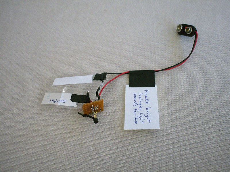
P1110597a
Schematic001
One of the previous You Tube videos I posted made reference to using an electronic circuit and oscilloscope for measuring the shutter speed of my 8" x 10" box camera's mechanical shutter. Since then I've been asked to provide more information on this circuit.

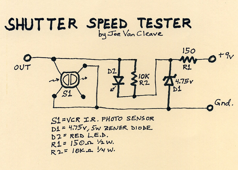
As can be seen above, the little circuit board has a handful of components, the most important being an optical sensor, salvaged some years ago from a VCR. This particular component has no identifying part number, and so I cannot give you any more information about sourcing a similar part, but a description might be helpful. It has four legs and two sections, an infrared-emitting diode section and an IR-sensitive photo-transistor section. In the schematic diagram I've drawn S1 as it appears when looking down at the sensor end of the device, with the four legs spread out underneath. It was originally used underneath the supply and take-up reel spindles in a VCR to sense rotation of the spindles. IR light emitted by the device would be reflected off a series of silver and black segments on the underside of a reel spindle, resulting in a square-wave output signal from the photo-transistor as the spindle rotates. The device is intended to be powered from a 5v TTL source.

The circuit is powered by a standard 9V battery, regulated down to just under 5v by means of resistor R1 and zener diode D1. Keep in mind that this circuit was made from spare parts I had on hand, so it's not optimized in design. In particular, the value of R1 (here 150 ohms) is determined by how much current is drawn by the photo-transistor device S1, and the zener diode. The lower the value of R1, the more wattage diode D1 will consume in trying to regulate the voltage to about 5 volts, thus determining how much wattage the diode needs to be rated at. I have the sense that I could have increased the value of R1 and used a lower wattage diode. If you decide to build something like this, you'll have to measure the current flowing out of R1 and calculate its optimal value accordingly. As it is, none of the parts draw enough power to get too hot, so at least I'm in the ballpark, design-wise.

Resistor R2 provides bias voltage for the photo-transistor portion of device S1. The red LED diode, D2, that's in parallel with R2, was added as a means of improving the biasing of S1; without D2, the device doesn't output as much of a signal.

The right-hand portion of S1 in the diagram is the IR-emitting diode, which is not needed in our application, so its power leg is left open.

In actual use, this circuit is intended to be used with an oscilloscope, on whose screen you can measure the pulse width resulting from the shutter firing and thereby calculate its speed. I also connect a volt meter across the output, as a way of verifying the output switches from its no-light condition of around 4.2 volts to below 1 volt when the sensor is hit with a bright source of infrared light. I connect the ground leads of both the meter and scope to "gnd," and the positive lead of the meter and scope probe to "out." A standard 9V battery is connected to power the circuit.

To calculate the shutter speed, measure on the scope the pulse width in graticule divisions (you might have to fiddle with triggering settings on your scope to get it to properly display when the shutter is fired), then multiply the number of divisions by the setting of the time base control. This tells you how many milliseconds the shutter is opened. To convert that into a practical fractional value usable with a light meter, take the pulse width in milliseconds and divide by 1000; then invert the result - this will be the fractional value of the shutter speed in seconds.

Example 1: the pulse width measures 125 milliseconds on the scope. 1/(125/1000) = 8. So your shutter speed is 1/8 second.

Example 2: the pulse width measures 112 milliseconds on the scope. 1/(112/1000) = 8.93. So your shutter speed is 1/8.93 seconds. You can see how representing the shutter speed as a fraction helps to determine the correct aperture required on your light meter, since I know of no meter that reads shutter speed in milliseconds of duration (at least my analog meters don't).

Since the sensor S1 is only infrared-sensitive, you'll have to use a bright source of IR light. I found a halogen flood lamp, at least 65 watts, will work well. You may have to adjust the angle of the light striking the sensor to optimize the output signal to be as low as possible when lit; that's what I use the meter for, prior to actually firing the shutter and using the scope.

I plan on installing this circuit into a housing, and adding a switch and output terminals, so the battery can be kept connected; this will make it more functional and practical.

I know there are other shutter speed testers that use a microphone and audio-editing software to measure the time duration of the sound made by the shutter. While this method might be accurate enough for curtain shutters found on film cameras, a shutter like mine doesn't make a distinctive enough start and stop sound to make audio measurements accurate. I have the sense that the same is true with any kind of leaf shutter. So an optical means of measuring shutter speed should be more accurate.

Let me know in the comments section below how your shutter speed tester project comes out.

Monday, January 11, 2016

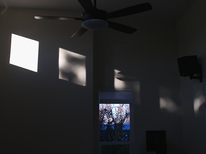
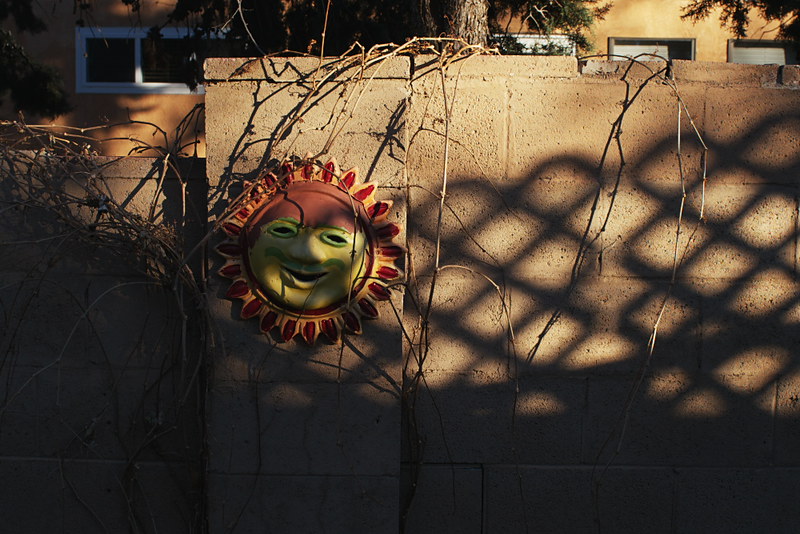
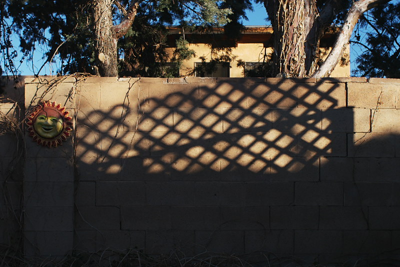
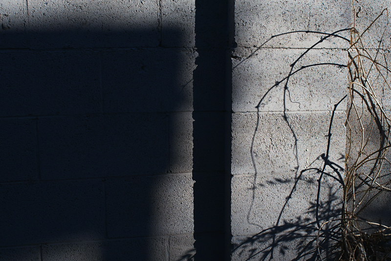
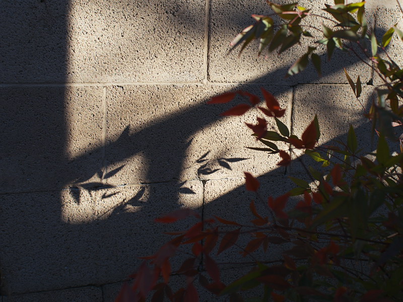
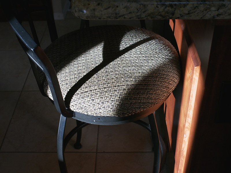
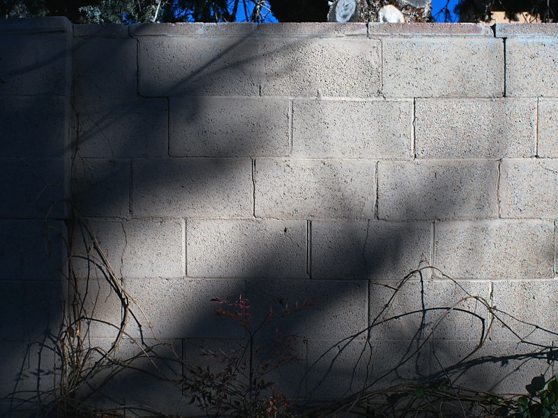
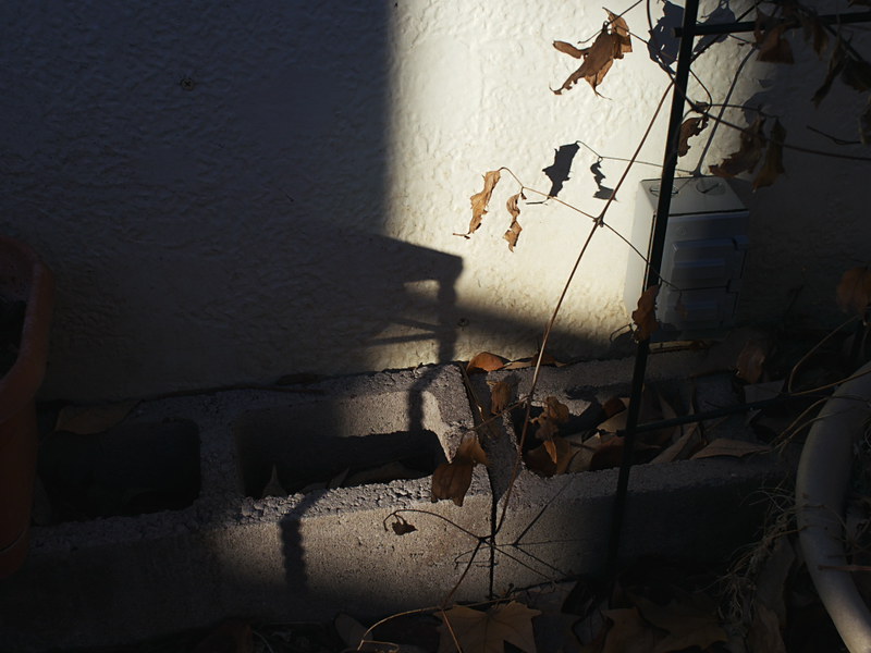
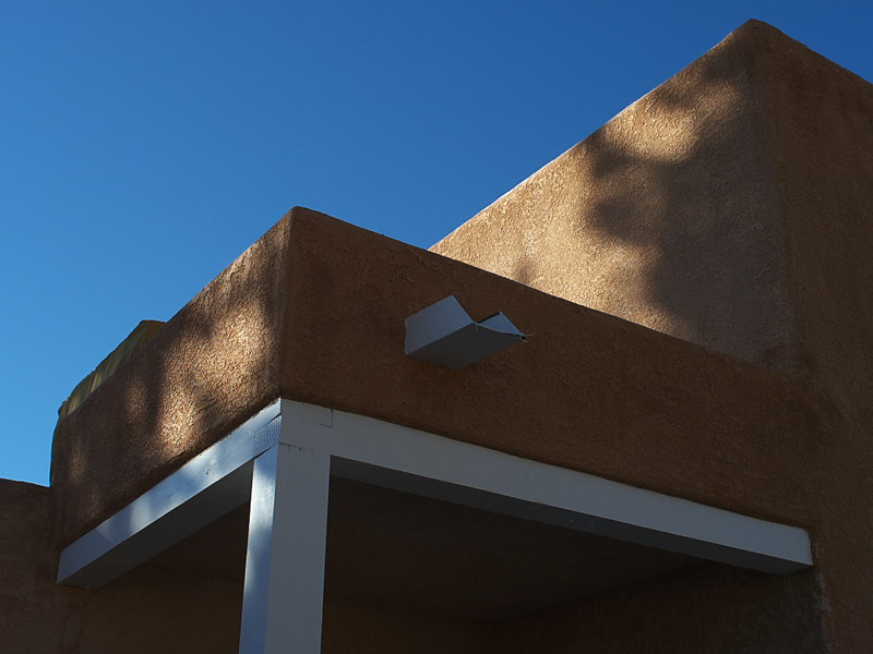
Shadow Play

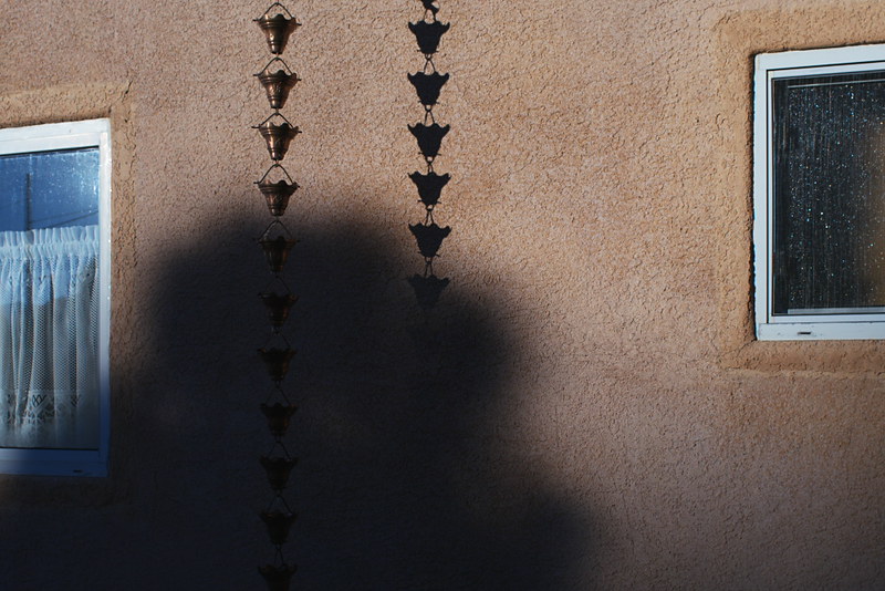
P1110547a
It is the mid-1990s and I'm sitting in the sunlit courtyard at work, on a break from the tedium of the factory, sipping on a cup of cafeteria coffee. I find the open air and bright sun to be cathartic, a healing gesture from the cloistered factory with its crowded machinery, yellow lights and incessant noise. I come here periodically, to clear my head and find some inner solace.

Yet, my mind is always curious, even during these times of relaxation. During these moments I would often let my mind drift, entering into a deeply creative mindset, pondering the nature of things; a precious state of mind that would otherwise be drowned out by one's incessant inner dialog or the distraction from things external; an ad hoc practice of daydreaming that proved, over time, to be extremely fruitful: inspiring over the subsequent years many of my most important photographic projects.

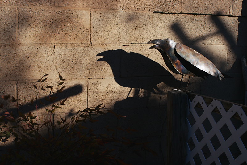
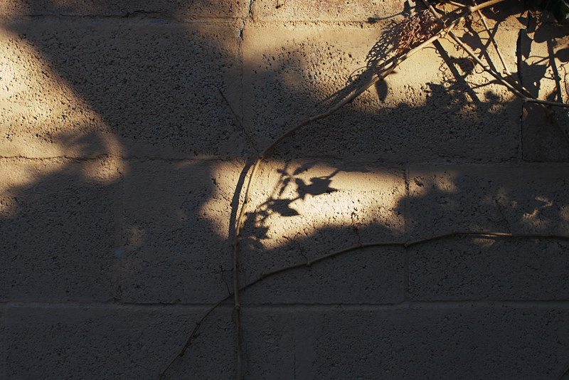
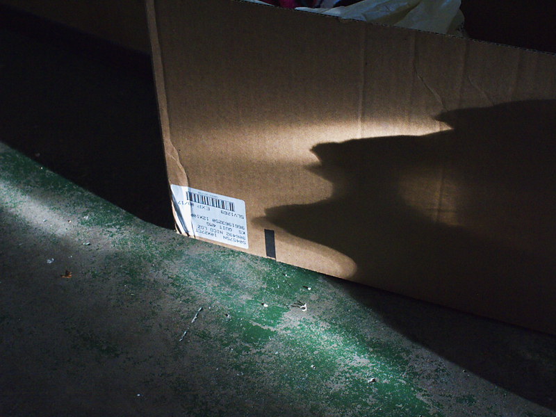
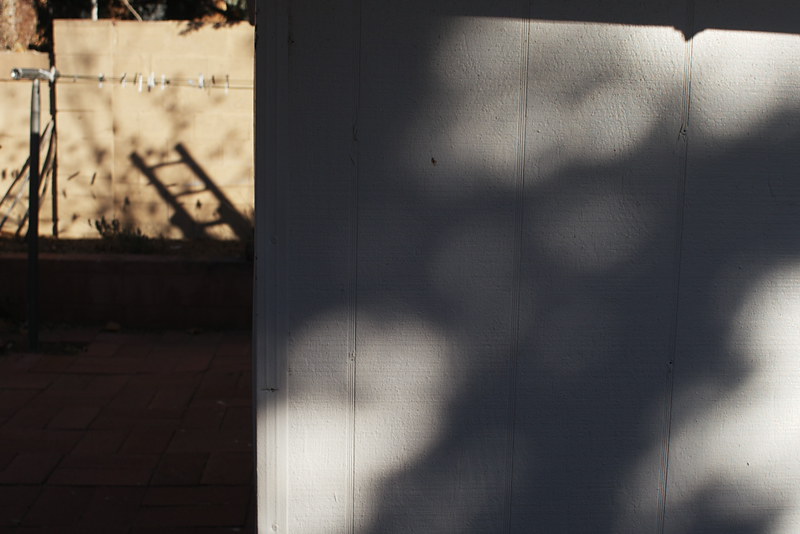
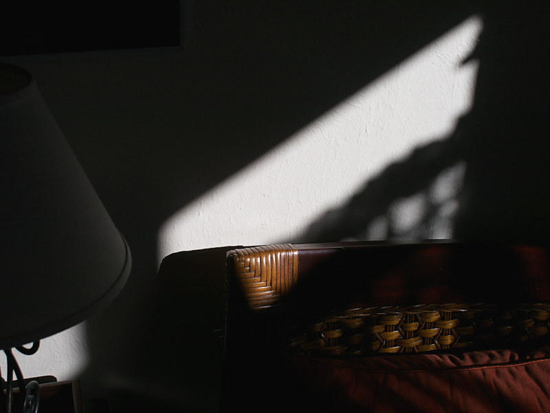
While sitting in the bright New Mexico sun, my mind quiet and alert, I had begun to notice the shadows cast by the outdoor furniture upon the concrete patio, how the slot-like openings in the benches, and grid of round holes in the tabletops, were each represented by their equivalent shadows below, similar enough in shape to be an accurate facsimile of their progenitor yet different, mainly in the way that the shadows' edges were modulated in sharpness, depending on the distance the shadow is cast from object to patio's surface.

What interested me in particular was how the shadows' edge sharpness could vary so much, from almost acutely sharp to distinctly out-of-focus soft, simply based on the shadow's projection distance. It reminded me so much of the kind of narrow depth-of-focus image seen from a lens operating wide-open - and yet no lens or even pinhole were being employed - and also amazed me that such optical effects could be observed through the simple act of careful study.

Thinking in more depth about what I was seeing, I came to realize that part of the reason for the edges of these shadows being less than razor sharp has to do with the fact that the sun, as the source of illumination, is itself not a point-source of light but is nearly 1/2 degree wide, a disc of light rather than a point, such that rays of photons striking the edge of an object do so from multiple directions, nearly parallel but not exactly so, thus casting a shadow whose edges are intrinsically soft. And also, that the further away from the object these shadows are cast, the more diffuse are the edges thus represented.

This effect is most pronounced when viewing the projection of shadows upon a flat surface from objects of disparate distances from one another. Here, distance information can be directly decoded merely by observing the shadows' edge sharpness, the resulting projected image taking on a quite unexpected but distinctly three-dimensional quality.

This quiet pastime of watching shadows play themselves out upon some theater-like projection screen of concrete patio became for me, over time, a kind of instructional classroom, tutored by light itself. Not only could one discern the three-dimensional characteristics of objects from their shadows alone, but the very nature of light itself was quietly yet inexorably being revealed. This was nowhere more pronounced when, a few years later, I had the opportunity to observe the light from a partial solar eclipse cast shadows upon the ground through the openings in a tree's canopy, each intersection of branch and leaf serving as a crude but effective pinhole-like aperture. I could observe the progress of the eclipse mirrored in the array of crescent-shaped spots cast upon the ground, nature's magic lantern show, broadcast in ultra-low-definition, free-for-view.

Eventually I came to build a mental model of what I was seeing, imagined as if I were living in a gigantic camera obscura, with the sun as an aperture moving across the sky, looking outward toward some mysterious field of brilliant, infinite light beyond, whose rays projected shadows of objects upon the far wall, that represented the earth and our material existence. The closer an object is to that earthen wall, the sharper its representation; while the closer to the source of light, the less distinct it becomes; as if, in that one observation, the entire spectrum of philosophic belief, from a materialistic, individual perspective to a cosmic consciousness, were represented.

On a more mundane level, these shadow studies also served over time as the genesis for further photographic experimentation, and were the main inspiration for my pursuit of pinhole photography.

One such experiment involved suspending objects inside a large pinhole box camera, then pointing the aperture of that camera straight upward, toward the sky, to model that mental picture I had imagined earlier, as a field of shadows chemically resolving themselves upon the earthiness of silver gelatin paper in the back of the box, like a snapshot taken of a shadow-puppet theater in action, the stage being the interior volume of the camera and the spotlight being the sun outside the box, projected inward via the pinhole aperture.

Further ideas along these lines merit more exploration. Puppet figures or paper cutouts could be suspended inside such a camera, left to slowly pirouette, mobile-like, over a period of time, leaving as a record of their movement mysterious shadows cast upon silver paper.

There's also the idea of the Cloud Camera, intended to capture daily (or as often as possible) upon silver paper images of the sky's appearance, using a simple pinhole camera pointed straight upward.

There are yet more thoughts left to ponder, more inspiration yet to be worked out from these humble musings upon the nature of light, as revealed through the study of mere shadows.

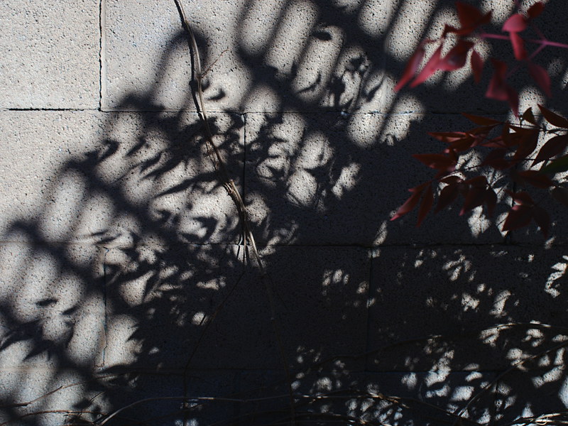
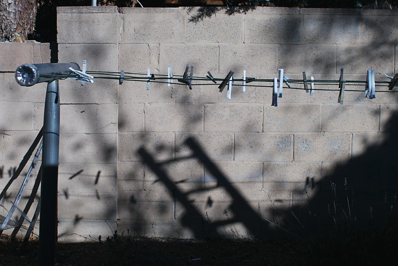
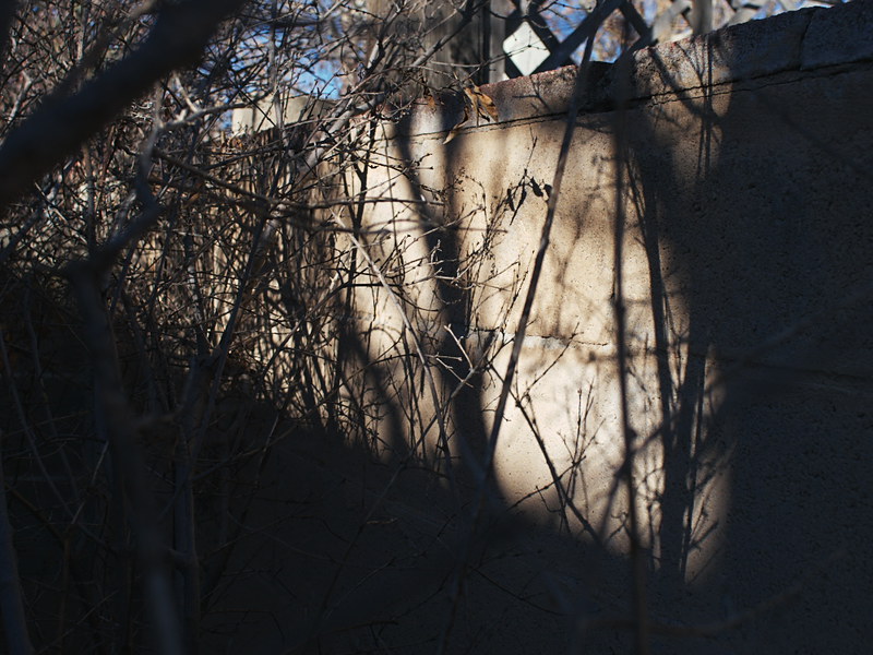
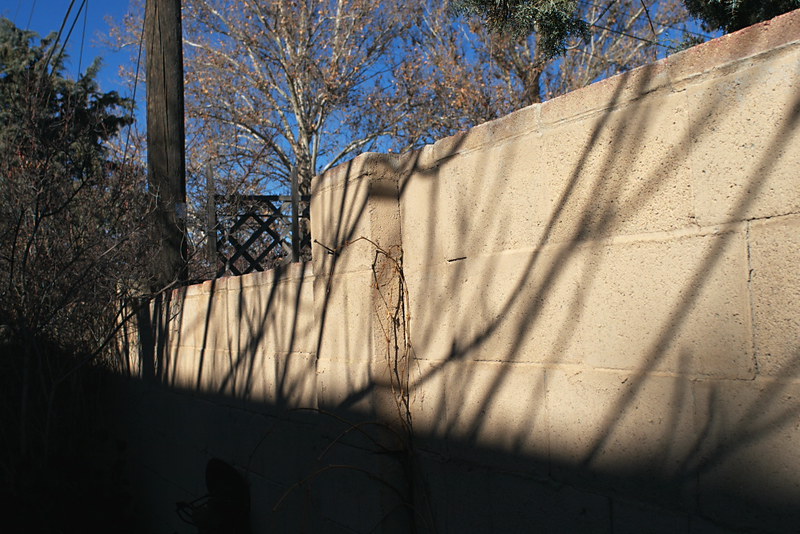
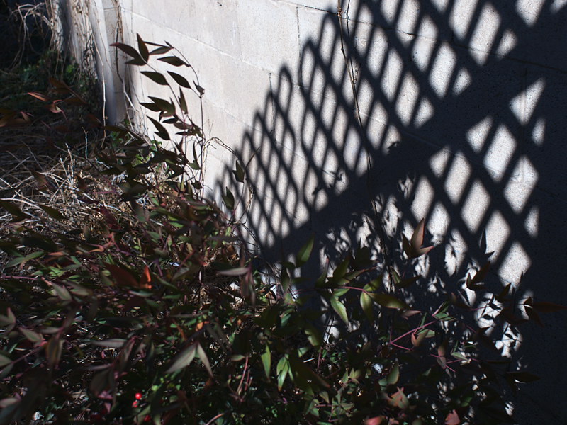
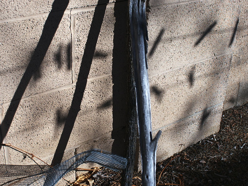
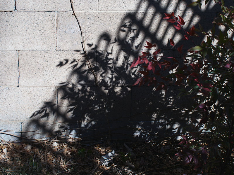
Even today, so many years removed from those days of long ago, I still marvel. Just this morning I was observing the shadows of shrub and trellis cast upon the backyard wall by the morning light, again making note of the variations in edge sharpness being dependent upon shadows' projection distance, once again finding myself in wonder at the seeming three-dimensionality of the resulting image, nature's original light writing, yet invisible to ordinary mortals who've yet to gain awareness of the nature of the shadow box that we all reside within.

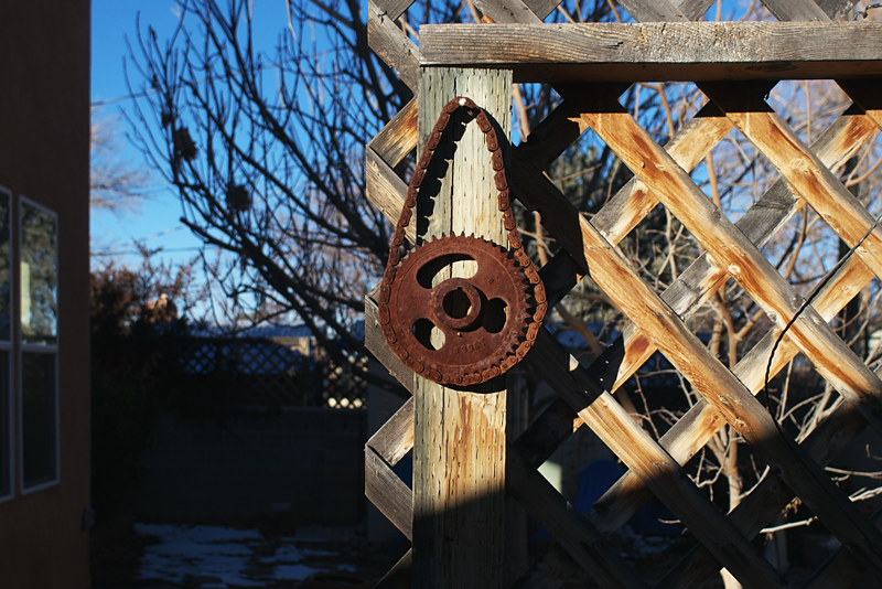
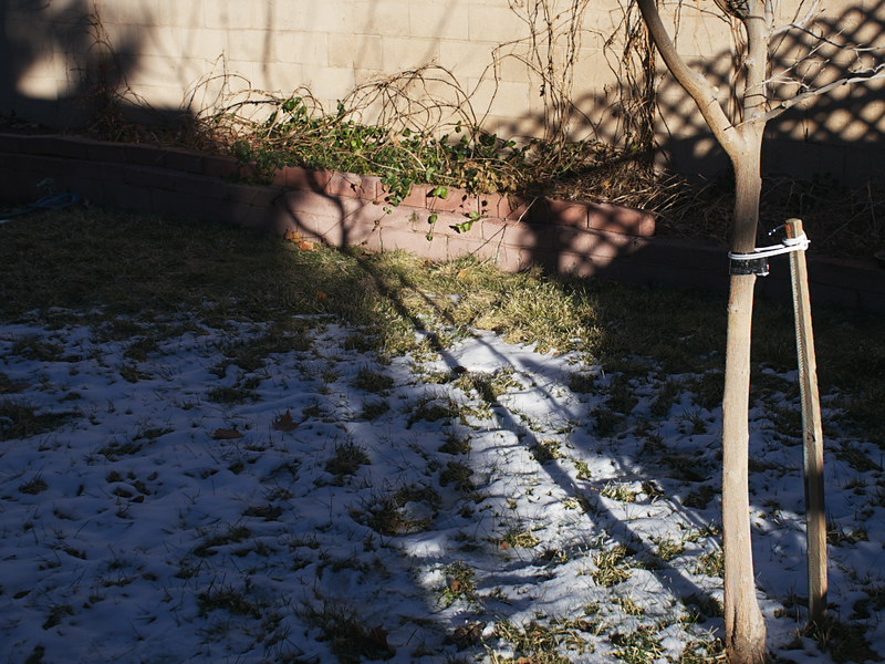
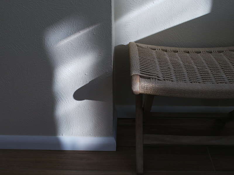
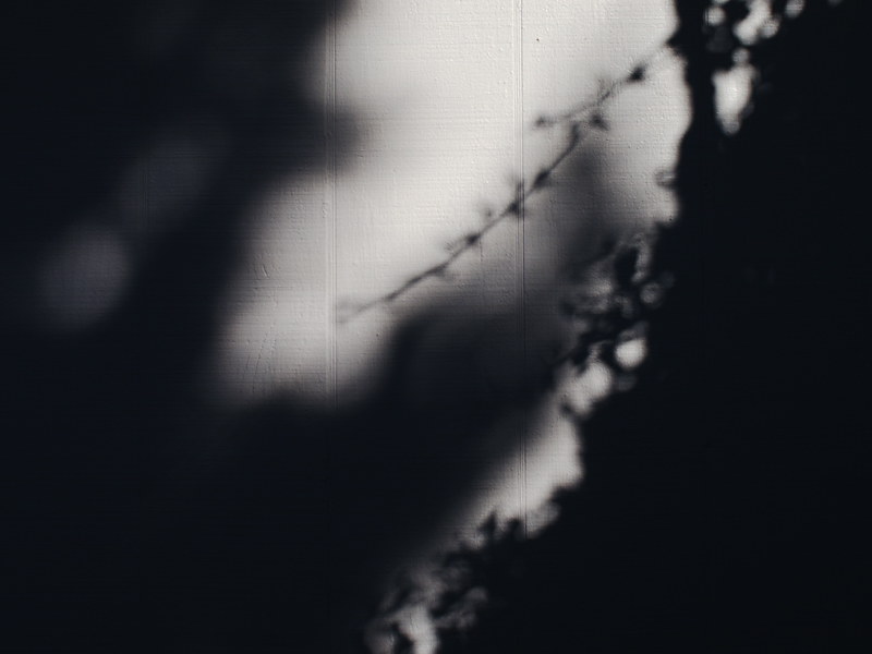
Post-Script: A series of Shadow Study images from this morning, created with the Lumix G5 camera and Vivitar 24mm-f/2.8 Minolta MD mount lens.

P1110483a
P1110484a
P1110486a
P1110488a
P1110492a
P1110501a
P1110504a
P1110506a
P1110507a
P1110510a
P1110516a
P1110518a
P1110519a
P1110523a
P1110526a
P1110527a
P1110528a
P1110533a
P1110535a
P1110537a
P1110539a
P1110541a
P1110543a
P1110545a
P1110549a
P1110550a

Wednesday, January 6, 2016

More Mechanical Shutter Stuff


I was anxious to do some testing of the mechanical shutter for the 8" x 10" lens box camera, that I had wrote about in the previous article, but due to the cloudy, snowy weather this last week I didn't have enough light. The mechanical shutter has a speed of about 1/8 second; combined with the slow speed of the Harman Direct Positive paper (I rate it's Exposure Index at around 7.5), that means you need a relatively wide aperture to get sufficient exposure, or find bright daylight.

But last week I did have a chance to eke out one test, in my front courtyard, under a sky streaked with high clouds, barely enough light to get sufficient exposure, but the test did come out fine, indicating that my measurements of the paper's sensitivity and the shutter's speed were fairly close.

I was also anxious to complete part two of the video series about this shutter, initially hoping to find bright, sunny conditions where I could simultaneously shoot more tests while also recording some video. But the weather didn't cooperate, it remaining cloudy and stormy this week, and so yesterday I decided to just do a speaking video about the shutter, describing in detail how I control exposure using the choice of aperture plate, rather than actually demonstrating it live under real-world conditions.

In the course of preparing for this second video, I had to figure out in more detail how I was going to manage exposure control with this shutter. It finally struck me that, with a fixed, single speed, I'd be operating the camera as if it were set to "shutter speed priority" mode - you have one shutter speed, and the paper's sensitivity is also fixed. So the only control one has over exposure is choice of aperture plates. But I only had a handful of such plates made, a choice of 34mm, 17mm, 9mm, 6mm and 3mm. I had to figure out how many other apertures I'd need, and of what sizes.

Thinking further about this, I finally realized that there are two "inputs" that determine the choice of aperture size: the camera's focal length, and the meter's recommended exposure.

In practice, as with any camera, these large format cameras require you to know the actual focal ratio of your lens, in order to properly determine the required exposure. But with these cameras, as you focus the lens by sliding the rear part of the box in and out of the front portion (or expand or contract a bellows, with a commercially-made large format camera), the focal length of the lens changes as you focus. Since focal ratio is focal length divided by aperture size, this means that with large format cameras, changes in focus will affect changes in exposure.

My camera is primitive enough that its lens doesn't have an f-stop control with a scale indicating focal ratio; even if it did, as with my Graflex Speed Graphic, you need to know the real aperture ratio, that takes into account the real focal length of the lens after it's been focused, especially when doing close-up work where the bellows might be extended out rather far from the default infinity focus distance. This hand made camera does include a measuring scale that indicates this actual focal length, however, and that should be sufficient.

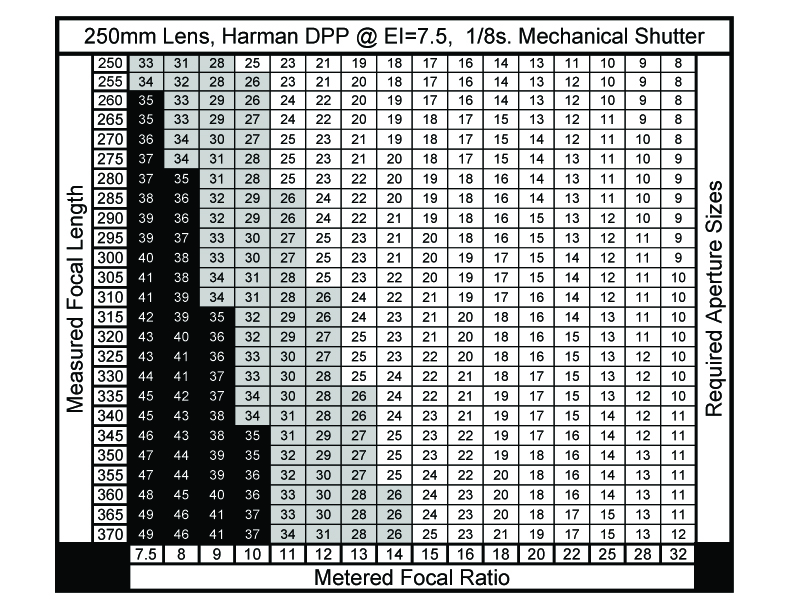
Mechanical_Shutter_Aperture_Table

So I finally figured out that it would be most helpful to have a chart, attached to the camera, that gives me the needed aperture sizes for any combination of real focal length and required focal ratio from the meter. I sat down and made such a chart using spreadsheet software, with the vertical axis being focal length and the horizontal axis being needed focal ratio. I rounded off the values in each cell to whole numbers, in keeping with the accuracy given in real-world conditions of reading the dial of an analog light meter.

The table yields all the required sizes of aperture plates needed to cover the range of exposures given by the meter, for the entire range of focal lengths of the camera. But I wasn't certain that I wanted to make all those additional aperture plates. For one, the values given in the lower left quadrant are hypothetical sizes, actually larger than the diameter of the lens currently in place, and so I blackened those cells out. Second, from 34mm down to about 26mm I figured the image would be noticeably blurry around the edges and corners, in keeping with the way meniscus lenses operate at nearly wide-open apertures, and so I grayed out those cells; I do have a 34mm plate, while if I choose to, more of these larger sized plates in the range from 26mm-34mm can be made later on, perhaps for making portraits.

The main body of the table gives aperture sizes from 25mm down to 8mm. Instead of making plates with every one of these sizes, I chose to make plates for every value in the top 250mm (infinity) focal length row. As I show in the video, there are now sufficient plates for virtually any required exposure within the range given.

I made these eleven additional plates using heavy black craft paper, reinforced with black gaffers tape, as I had done previously with some of the other plates. I cut the holes using a compass cutter, a craft tool that operates like a draftsman's compass but uses a thin knife blade in place of the lead point. All nested together in one stack, bundled with an elastic band, they can easily be stored inside the camera during transport.

More work is required, of using this system to make real-world images in various kinds of light, before I can say it's entirely practical. But my initial courtyard test image shows promise.

Going forward, it would be nice to have a more sophisticated shutter, with actual variable (and accurate) speeds to choose from; but that will have to wait for another day.