Showing posts with label mechanical shutter. Show all posts

Tuesday, January 12, 2016

Shutter Speed Tester

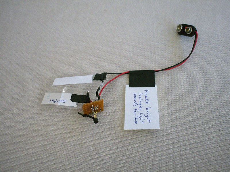
P1110597a
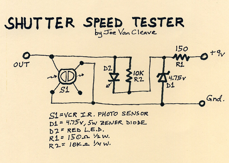
Schematic001
One of the previous You Tube videos I posted made reference to using an electronic circuit and oscilloscope for measuring the shutter speed of my 8" x 10" box camera's mechanical shutter. Since then I've been asked to provide more information on this circuit.

As can be seen above, the little circuit board has a handful of components, the most important being an optical sensor, salvaged some years ago from a VCR. This particular component has no identifying part number, and so I cannot give you any more information about sourcing a similar part, but a description might be helpful. It has four legs and two sections, an infrared-emitting diode section and an IR-sensitive photo-transistor section. In the schematic diagram I've drawn S1 as it appears when looking down at the sensor end of the device, with the four legs spread out underneath. It was originally used underneath the supply and take-up reel spindles in a VCR to sense rotation of the spindles. IR light emitted by the device would be reflected off a series of silver and black segments on the underside of a reel spindle, resulting in a square-wave output signal from the photo-transistor as the spindle rotates. The device is intended to be powered from a 5v TTL source.

The circuit is powered by a standard 9V battery, regulated down to just under 5v by means of resistor R1 and zener diode D1. Keep in mind that this circuit was made from spare parts I had on hand, so it's not optimized in design. In particular, the value of R1 (here 150 ohms) is determined by how much current is drawn by the photo-transistor device S1, and the zener diode. The lower the value of R1, the more wattage diode D1 will consume in trying to regulate the voltage to about 5 volts, thus determining how much wattage the diode needs to be rated at. I have the sense that I could have increased the value of R1 and used a lower wattage diode. If you decide to build something like this, you'll have to measure the current flowing out of R1 and calculate its optimal value accordingly. As it is, none of the parts draw enough power to get too hot, so at least I'm in the ballpark, design-wise.

Resistor R2 provides bias voltage for the photo-transistor portion of device S1. The red LED diode, D2, that's in parallel with R2, was added as a means of improving the biasing of S1; without D2, the device doesn't output as much of a signal.

The right-hand portion of S1 in the diagram is the IR-emitting diode, which is not needed in our application, so its power leg is left open.

In actual use, this circuit is intended to be used with an oscilloscope, on whose screen you can measure the pulse width resulting from the shutter firing and thereby calculate its speed. I also connect a volt meter across the output, as a way of verifying the output switches from its no-light condition of around 4.2 volts to below 1 volt when the sensor is hit with a bright source of infrared light. I connect the ground leads of both the meter and scope to "gnd," and the positive lead of the meter and scope probe to "out." A standard 9V battery is connected to power the circuit.

To calculate the shutter speed, measure on the scope the pulse width in graticule divisions (you might have to fiddle with triggering settings on your scope to get it to properly display when the shutter is fired), then multiply the number of divisions by the setting of the time base control. This tells you how many milliseconds the shutter is opened. To convert that into a practical fractional value usable with a light meter, take the pulse width in milliseconds and divide by 1000; then invert the result - this will be the fractional value of the shutter speed in seconds.

Example 1: the pulse width measures 125 milliseconds on the scope. 1/(125/1000) = 8. So your shutter speed is 1/8 second.

Example 2: the pulse width measures 112 milliseconds on the scope. 1/(112/1000) = 8.93. So your shutter speed is 1/8.93 seconds. You can see how representing the shutter speed as a fraction helps to determine the correct aperture required on your light meter, since I know of no meter that reads shutter speed in milliseconds of duration (at least my analog meters don't).

Since the sensor S1 is only infrared-sensitive, you'll have to use a bright source of IR light. I found a halogen flood lamp, at least 65 watts, will work well. You may have to adjust the angle of the light striking the sensor to optimize the output signal to be as low as possible when lit; that's what I use the meter for, prior to actually firing the shutter and using the scope.

I plan on installing this circuit into a housing, and adding a switch and output terminals, so the battery can be kept connected; this will make it more functional and practical.

I know there are other shutter speed testers that use a microphone and audio-editing software to measure the time duration of the sound made by the shutter. While this method might be accurate enough for curtain shutters found on film cameras, a shutter like mine doesn't make a distinctive enough start and stop sound to make audio measurements accurate. I have the sense that the same is true with any kind of leaf shutter. So an optical means of measuring shutter speed should be more accurate.

Let me know in the comments section below how your shutter speed tester project comes out.

Wednesday, January 6, 2016

More Mechanical Shutter Stuff


I was anxious to do some testing of the mechanical shutter for the 8" x 10" lens box camera, that I had wrote about in the previous article, but due to the cloudy, snowy weather this last week I didn't have enough light. The mechanical shutter has a speed of about 1/8 second; combined with the slow speed of the Harman Direct Positive paper (I rate it's Exposure Index at around 7.5), that means you need a relatively wide aperture to get sufficient exposure, or find bright daylight.

But last week I did have a chance to eke out one test, in my front courtyard, under a sky streaked with high clouds, barely enough light to get sufficient exposure, but the test did come out fine, indicating that my measurements of the paper's sensitivity and the shutter's speed were fairly close.

I was also anxious to complete part two of the video series about this shutter, initially hoping to find bright, sunny conditions where I could simultaneously shoot more tests while also recording some video. But the weather didn't cooperate, it remaining cloudy and stormy this week, and so yesterday I decided to just do a speaking video about the shutter, describing in detail how I control exposure using the choice of aperture plate, rather than actually demonstrating it live under real-world conditions.

In the course of preparing for this second video, I had to figure out in more detail how I was going to manage exposure control with this shutter. It finally struck me that, with a fixed, single speed, I'd be operating the camera as if it were set to "shutter speed priority" mode - you have one shutter speed, and the paper's sensitivity is also fixed. So the only control one has over exposure is choice of aperture plates. But I only had a handful of such plates made, a choice of 34mm, 17mm, 9mm, 6mm and 3mm. I had to figure out how many other apertures I'd need, and of what sizes.

Thinking further about this, I finally realized that there are two "inputs" that determine the choice of aperture size: the camera's focal length, and the meter's recommended exposure.

In practice, as with any camera, these large format cameras require you to know the actual focal ratio of your lens, in order to properly determine the required exposure. But with these cameras, as you focus the lens by sliding the rear part of the box in and out of the front portion (or expand or contract a bellows, with a commercially-made large format camera), the focal length of the lens changes as you focus. Since focal ratio is focal length divided by aperture size, this means that with large format cameras, changes in focus will affect changes in exposure.

My camera is primitive enough that its lens doesn't have an f-stop control with a scale indicating focal ratio; even if it did, as with my Graflex Speed Graphic, you need to know the real aperture ratio, that takes into account the real focal length of the lens after it's been focused, especially when doing close-up work where the bellows might be extended out rather far from the default infinity focus distance. This hand made camera does include a measuring scale that indicates this actual focal length, however, and that should be sufficient.

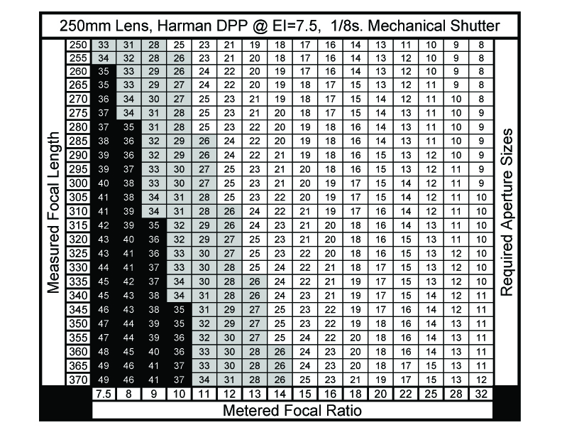
Mechanical_Shutter_Aperture_Table

So I finally figured out that it would be most helpful to have a chart, attached to the camera, that gives me the needed aperture sizes for any combination of real focal length and required focal ratio from the meter. I sat down and made such a chart using spreadsheet software, with the vertical axis being focal length and the horizontal axis being needed focal ratio. I rounded off the values in each cell to whole numbers, in keeping with the accuracy given in real-world conditions of reading the dial of an analog light meter.

The table yields all the required sizes of aperture plates needed to cover the range of exposures given by the meter, for the entire range of focal lengths of the camera. But I wasn't certain that I wanted to make all those additional aperture plates. For one, the values given in the lower left quadrant are hypothetical sizes, actually larger than the diameter of the lens currently in place, and so I blackened those cells out. Second, from 34mm down to about 26mm I figured the image would be noticeably blurry around the edges and corners, in keeping with the way meniscus lenses operate at nearly wide-open apertures, and so I grayed out those cells; I do have a 34mm plate, while if I choose to, more of these larger sized plates in the range from 26mm-34mm can be made later on, perhaps for making portraits.

The main body of the table gives aperture sizes from 25mm down to 8mm. Instead of making plates with every one of these sizes, I chose to make plates for every value in the top 250mm (infinity) focal length row. As I show in the video, there are now sufficient plates for virtually any required exposure within the range given.

I made these eleven additional plates using heavy black craft paper, reinforced with black gaffers tape, as I had done previously with some of the other plates. I cut the holes using a compass cutter, a craft tool that operates like a draftsman's compass but uses a thin knife blade in place of the lead point. All nested together in one stack, bundled with an elastic band, they can easily be stored inside the camera during transport.

More work is required, of using this system to make real-world images in various kinds of light, before I can say it's entirely practical. But my initial courtyard test image shows promise.

Going forward, it would be nice to have a more sophisticated shutter, with actual variable (and accurate) speeds to choose from; but that will have to wait for another day.

Thursday, December 31, 2015

Mechanical Shutter Experiments


Earlier this week I created another photography video, this time about the experimental shutter I built, some years ago, for the 8" x 10" box camera.

The genesis of this project was having used paper negatives in improvised lens cameras and finding that, due to the speed of the paper (I rate Freestyle Photo's Arista grade 2 RC paper at an exposure index of 12), I'd have to stop down the lens to a very small (2-3mm) aperture, in order to make the shutter speed long enough (>1 second) to accurately and repeatedly time by a hand-operated shutter, in bright daylight landscape conditions.

Under dimmer kinds of light, like window light, I've made a number of satisfying indoor still-life exposures in the daytime, where these improvised lenses, operating at wider apertures, display some interesting optical effects that make the resulting images rather special. But under bright daylight they have to be stopped down so much, in order for their exposures to be timed by hand, that they come to resemble hybrid pinhole/lens optics, lacking those optical aberrations I've come to appreciate from adapted optics, like binocular objectives and meniscus lenses.

So it seemed that I'd need some kind of shutter mechanism. But how?

I spent a long time cogitating about simple mechanical shutters, and ended up making a series of proof-of-concept sketches over several years, trying to find some design that might prove workable. In the end, I felt that I just had to start building something, and so it became a design-as-you-build kind of project, using scrap bits of hardware I'd collected over the years; my motto being something along the lines of never throw anything away, you might use it someday.

What I was trying for was a shutter whose speed could be varied over some practical speed range, to account for differences in exposure. Many of the early designs I considered were simple slit shutters, operated by spring tension and moving either horizontally or vertically, with the width of the slit accounting for the variation in exposure. But I soon realized that with a fixed spring tension a variable slit shutter operating up front at the lens would only yield a small range of speed variations.

After some time I realized that I could make the traveling slit camera into a rotary blade camera, and by altering the angle between the blades the timing could be adjusted. However, my initial idea was much more grand: by slowing down the speed of rotation, I could have a wider range of speeds, from multi-seconds long to fractions of a second, perfect for paper negative media.

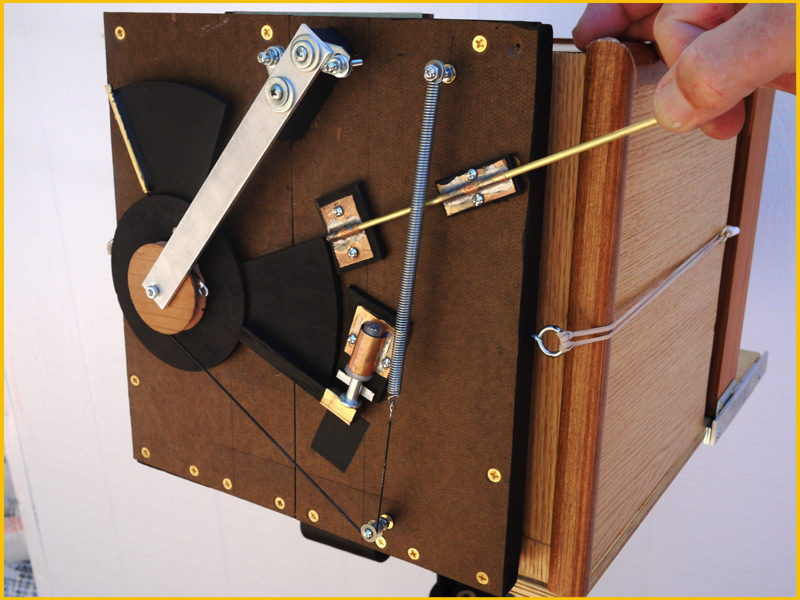
P1080490a
But I never got far enough along with this design to build a practical mechanism for slowing down the rotation while making its speed reliable and repeatable. The one big idea I had for this was based on a mechanism I'd seen years earlier, while repairing a Technics audio cassette deck, which was the method used to dampen the speed of the cassette door when it was ejected. Most cassette players used a simple plastic dash-pot mechanism, a piston and cylinder, with an o-ring and some grease, so that as the spring tension tries to slam the door open, the air in the piston is released in a controlled fashion through a small opening, allowing instead the door to slowly and smoothly open. The problem with this design is when the grease hardens up over time, and the cassette door slams open uncontrollably.

Panasonic's method was different. They used a small brass whirligig, a 4-vane rotating piece that was driven to rotate by a drawstring band attached to the door mechanism. As the spring tries to forcefully slam open the door, the band rapidly spins the whirligig, the resulting air pressure slowing down and regulating the speed of the door into a smooth motion. The best part of this design was its reliability, as there were no lubricants to harden over the years.

So my idea for the shutter was to employ this whirligig mechanism, in a small but rapidly turning pulley with vanes, that the shutter cord would spin as the shutter was moving, helping to keep the speed constant. In theory, it sounds plausible; but I never got to the point of implementing it with this shutter.

As you note from the video, the problem with this shutter is that the three speed adjustments, that alter the angle between the blades, don't really offer much variation in speed; and there's too much friction in the mechanism, caused by the way I designed for compensating for light leaks.

The sad thing about this project is that it's sat dormant for some years, as I just couldn't find the motivation to get back to improving it. But now, with these You Tube videos and this blog, perhaps I've painted myself into a corner whereby now I'm forcing myself to get back and finish these projects. And that's a good thing.

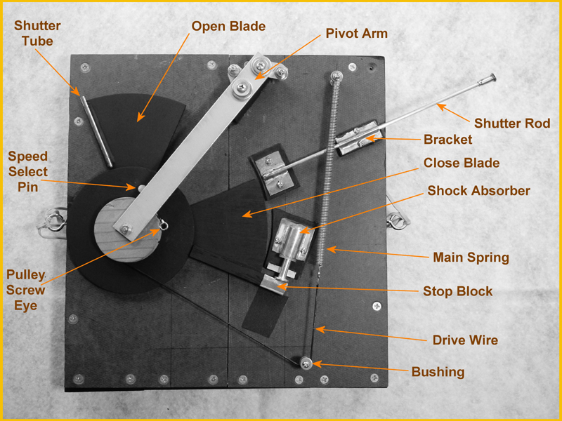
Here is a detailed photo of the shutter with the parts labelled, made a few years back; note that I've more recently changed the draw cord from a thin black to thick white cord.

P1080477b
This video was the first of two parts; next week I hope to take the camera out, with shutter attached, and make some usable images. Stay tuned.