As I indicated when I started this new blog, it will not only include pinhole images but also camera-making articles. And as I alluded to in the previous article, I had begun to employ falling plate cameras as a solution to the problem of taking a camera, of modest weight, out into the field and being able to expose multiple images, absent the additional weight, bulk and expense of multiple sheet film holders.
The first such camera, that pioneered the whole falling plate concept for me (and which I'll cover in a future article) was a large wooden box, employing an 8"x8" square format, built in the late 1990s; while the second such falling plate camera I built was a much smaller sheet metal camera with a 4"x4" format size. Although I did enjoy composing in square format, I had decided that for my third falling plate camera I'd employ a more rectangular format, better suited to landscape images. Since I had begun to purchase sheet film and paper in 8"x10" sizes, it made sense to cut these sheets in half to make negatives of 5"x8" size.
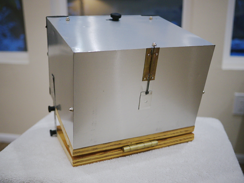
This new camera was constructed of an inner wooden frame, sheathed in aluminum flashing, using JB Weld epoxy for adhesion; thus being very lightweight for its size. This would eventually prove to be an issue regarding stability atop a tripod in windy conditions, which I hadn't yet realized, but would eventually be mitigated with the heavy, hinged plywood base, used to tilt the camera at various angles for use atop a non-adjustable tripod. With this combination of lightweight construction and a heavy, rigid base, the result is a rigid but lightweight large-format box camera.
As you can see from the top picture, the shutter is actuated by pulling up on the front viewing nut, which operates a guillotine-style shutter via a wire rod. Here's a closeup of the shutter in the opened position:
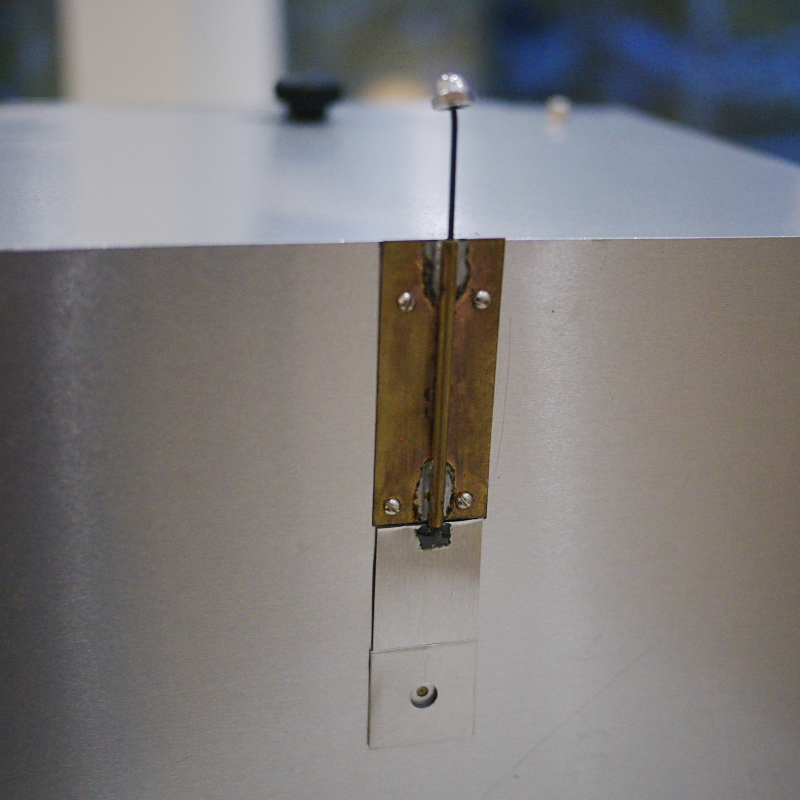
The shutter guide is soldered from sheet brass and attached to the camera front with small machine screws, while the attachment of the rod to the aluminum shutter piece is with JB Weld epoxy.
Here's a side view of the camera:
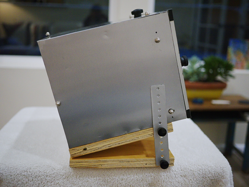
The hinged plate is oriented to point the camera down at an adjustable angle. I had found that for virtually all of my landscape images I tended to locate the horizon in the middle or upper third, hence the reason for the downward-pointing orientation of the camera. I think the reason for this is because I have been using orthochromatic film and paper that is ultra-sensitive to blue and UV light, meaning the skies are usually blown out, leaving little or no detail; what I call a "19th century" look.
You'll also note the triangle of viewing nuts along the side, for determining the vertical limits of the image; there's an equivalent set of nuts atop the camera, for determining the horizontal angle of view (with the front top nut also functioning as the shutter knob). You'll also note a smaller set of ink dots adjacent to each rear viewing nut; these were put in place after I had subsequently enlarged the film format size of this camera. It was originally intended for 5"x8" sized images, but later I figured out that I could fit 6.5"x9" negatives on the same plates; a bit more wasteful of film (since there results in wastage when cut from an 8"x10" sheet) but enabling larger images.
Here's a rear view of the camera:
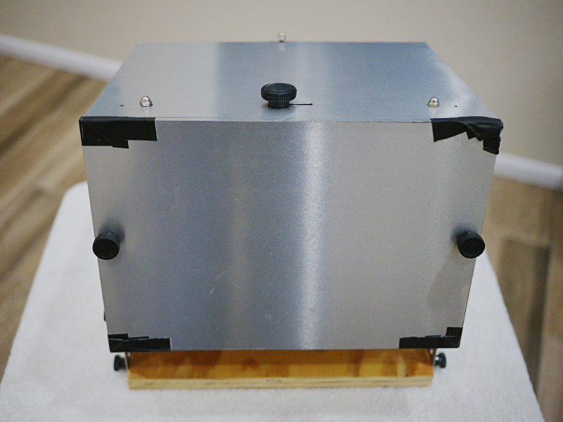
Note the two knobs, used to remove the back panel. Atop the camera are the three viewing nuts, and the film changing knob in the middle, that slides alternately left and right to drop the front film plate after exposure. Note the black gaffers tape in the corners, applied because the thin aluminum strips glued to the edges of the back lid began to come loose after several years of heavy use. Here's a view of the inside with the back lid removed:
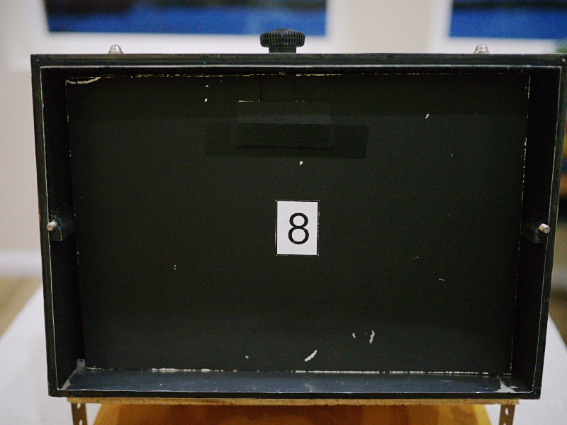
Note that there are eight film plates currently installed. The sheet film or paper is taped to the front side of each plate, using several loops of drafting tape, which are easily removable without harming the film or paper. Not shown is a heavy sheet of galvanized steel, set behind the number 8 plate and used to push the plates forward against the retaining pin, which helps to ensure reliable operation of the film changing mechanism. There's also a thin lip along the bottom edge that the stack of plates pushes against, that's about 1/4" high (seen next to the lower left corner of the number 8 plate). The gap between the top of the plates and the inside ceiling of the camera is less than 1/4", and thus as long as the plates stay firmly pressed against the upper pin and lower lip, they will stay in place.
The plates each have a notch cut in the upper edge, that alternate left and right, thusly:
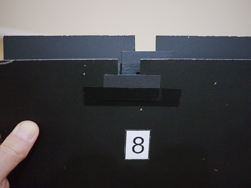
Here you can see the number 8 plate's slot is toward the left, with the number 7 plate behind it and whose notch is toward the right. The changing knob operates a pin that protrudes into the camera, that engages those slots. The thin ceiling of the camera has a light-tight area where a thin piece of wood slides back and forth, to serve as a light baffle for the knob-to-pin penetration. Here's the knob and pin in close-up:
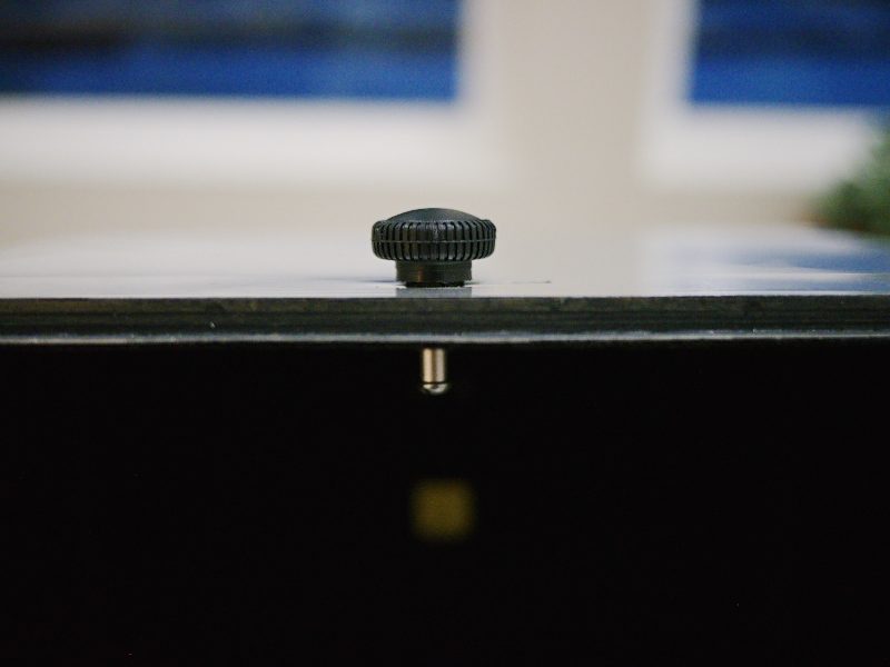
Note that the pin is made of a machine screw and aluminum spacer tube, whose overall length is such that the plates' notches will easily clear the pin when required to fall.
Operating this camera requires first setting the box atop the tripod, and keeping it generally upright as I hike around. With the tripod over my shoulder and pinhole pointing slightly downward, the exposed and unexposed plates will generally stay in their proper places. The problem with the unexposed plates is if they become dislodged from the shelf they normally sit upon; while the problem with the exposed plates is if they become dislodged from the floor of the camera enough to block the view of the pinhole, or prevent subsequent plates from properly falling.
I had learned after much experience that it was easier to carry camera atop tripod with the legs of the tripod already extended and spread out, in case I suddenly needed both hands free and had to set down the load, as it would support itself on the ground without toppling over; I thus found it easiest to carry the tripod with two of its legs straddling my neck.
I'd also carry a light backpack on my shoulders, with light meter and other accessories such as pen, pad, and water bottle. Once the tripod was situated for a shot, I'd hang the backpack from the tripod to increase its stability in the wind.
As I indicated earlier, this camera initially didn't have the heavy wooden hinged base, and therefore would easily flex in the breeze, causing the images to be blurrier than normal. The addition of the heavy base fixed that problem, while also providing for an adjustable vertical angle; because one tripod option I had available was a homemade 48" tall non-collapsing tripod made from tropical hardwood dowels, very light in weight but also lacking an adjustable head. I could adjust its leg positions to get the horizon level, left-to-right, and then adjust the camera base for the vertical angle. This proved to be much easier to carry than my heavy Bogen tripod. I'll make a post about the tripod in a future installment.
Overall, this was one of the better cameras I ever made, as future images from this box will prove.
Thanks for reading.
~Joe
No comments:
Post a Comment
Please leave a comment; I will curate them before posting.