Showing posts with label DIY. Show all posts

Monday, February 8, 2016

Wide Angle Direct Positive Work

P1110673a
There was a time, several years ago, when I decided to make yet another pinhole camera, this one being a one-shot box camera made from "chipboard" cardboard (available in packs at Michael's crafts store) and gaffers tape. Using a paper size of 4"-by-5", and an image area of 3.5" square, its principal feature was a very wide angle of view. I had used this camera briefly, with paper negatives, then set it aside for a time.

Then last week I had a hankering to work again with this camera, only instead of using paper negatives I wanted to try Harman's Direct Positive paper, which I have been using extensively these last few months in other cameras, having arrived at a more accurate working exposure index and development methodology.

I created two images that day, exposed with my usual method of rating its ISO speed at 8 and metering the scene reflectively. I reference the exposure time on my meter opposite F/128, then multiply that by the camera's "X-value", marked on the front of the camera, that adjusts for the camera's true focal ratio, to arrive at the working exposure time.

P1110671a
For this first image, of a tree in a front yard along a neighboring street, in the morning light, the meter indicated 15 seconds at F/128, while the actual exposure, taking into account the camera's actual focal ratio using the "X-value" multiplier, was 47 seconds. To make the setup small and convenient to carry, I didn't bring a regular tripod during this morning walk but rather just a tabletop mini-tripod, which I set on the ground in front of this tree, looking upward. I had to ensure that I stayed out of the way of the pinhole's field of view after sliding open the cardboard shutter, given the extra wide angle of view of this short camera. Metering was done against the brightly lit front part of the tree trunk.

Inspiration for this image was found that previous evening, during a stroll, when I noticed the stark, barren branches illuminated by the dim light of a street lamp.

P1110672a
This next image was created after returning from this morning walk, of a pot near my front courtyard, again taken from a ground-level perspective, with the camera atop the mini-tripod. The meter indicated 10 seconds at F/128, while the actual exposure was 32 seconds.

Several aspects of these images interest me. For one, there's the extremely wide angle of view, causing the severe vignetting. I like the way that the central image area seems framed in a surrounding area of blackness. Also, the sky in the first image appears to be nicely dark in tone, rather than the usual blown-out whiteness when using orthochromatic paper media.

Both of these aspects are actually interrelated, since the reason for the relatively dark sky tones is because of the light falloff caused by that severe vignetting. Were the camera of a "normal" angle of view (where the focal length is about the same as the format size) there would be much less vignetting and light falloff toward the edges, resulting in a much more over-exposed sky.

This is an important point to consider when designing a pinhole camera for scenic photography that's intended to be employed using orthochromatic paper media. The severe light falloff caused by these short focal length, wide-angle cameras can serve to darken the edges and corners sufficiently to render the sky with a more pleasing, darker tone, more like what we'd expect using panchromatic film.

Of course, when doing so one must also accept the resulting severe foreshortening effect of such wide-angle optics, rendering objects even relatively near the camera rather diminutive in size, unless they are only inches away from the aperture.

It is possible to find a reasonable compromise with angle-of-view, that renders objects with a more normal perspective while still affecting some degree of light falloff sufficient to render a bit of sky detail visible. In my experience this occurs in angles of view somewhere in the range between 90 and 120 degrees. Some experimentation is required, for your individual needs. A handy rule of thumb is that a 90-degree angle-of-view occurs when the film or paper is twice as wide as the focal length.

These little 3.5" square prints will work very nicely when matted to a larger frame size, and I can see an entire series being presented in this manner. What makes this possible is the refinement in my process that I've worked toward, from camera to finished print via rotary processing of Harman Direct Positive paper.

Monday, February 1, 2016

Custom Roller Base Project

P1110635a
For a few years now, I've been working with the Harman Direct Positive Paper, a silver gelatin, fiber based, black & white print paper that has a direct positive emulsion, meaning that it can be directly exposed inside of a camera to produce, after development using standard chemistry, a one-of-a-kind print. There was a point in time, for about a year, when the paper was out of manufacture, due to a chemical supplier going out of business and another source having to be found, but now it's once again being made, and supplies are plentiful.

I've created one-of-a-kind prints using this medium in a variety of sizes, from sub-miniature Minox-sized to 8"-by-10". While the larger formats require either tray development in a darkroom setting or a large processing drum, and the Minox-sized prints were best handled in small containers in a darkroom, it is in those intermediate-sized formats, from 35mm to 4"-by-5", that I've done most of my work with this paper, and hence would like to find more convenient working methods.

One of the main issues I have is during the winter months, when my unheated, garage-based darkroom requires considerable time to warm up using a space heater, precluding spur-of-the-moment boughts of darkroom creativity. What I'd like is at least a way to work with the Harman paper in the convenience of my kitchen.

While I do have a Jobo processing drum for 4"-by-5" prints, the associated manual roller base is a rather pricey and fragile item. However, for smaller-sized prints - such as those cut to custom sizes for loading, one-at-a-time, into small and medium format cameras - there is no custom-fit processing tank available.

Several years ago, in a fit of inspiration, I decided that I might be able to use a stainless steel 35mm developing tank as a makeshift rotary processor for these special-sized smaller prints. The idea was that the reels would be kept inside the tank and the paper would be slipped into the gap between the outside of the reels and the inner surface of the tank, with the emulsion facing inward. With the lid installed, an adequate quantity of chemicals - about 100mL - can be used for processing without sloshes spilling from the lid, as the tank is oriented sideways and continuously rotated.

What I needed to make this work was a roller base. I had the Jobo base for my larger formats, and I figured out how to rearrange the roller brackets to make it work somewhat for the smaller steel tank, but I wanted a dedicated solution, so I wouldn't have to keep re-configuring the Jobo roller base; it being made of plastic, I was concerned the pieces would eventually break.

And so last week I went to the hardware store and looked for some caster wheels. I noticed there were three kinds, two of which were unusable because the wheels swiveled on bearings. I wanted wheels that rolled on a fixed support mount but didn't swivel. I found what I was looking for, and went immediately to my workshop to begin fashioning the roller base.

I first had to figure out how to properly space the four wheels. So I used an old scrap piece of plywood as a test base and, using clamps, tried various configurations with the wheels and steel tank until I found an optimal configuration where the tank easily rolled on the wheels. I then measured the positions of the wheel brackets and transferred those measurements to the nice piece of plywood, that I had prepared ahead of time by spray painting a metallic silver color.

I countersunk flathead screws through the bottom of the base, with the holes tapped to fit, and used nylon locking nuts to secure the wheels. The bottom I covered in a sheet of rubber matting material via a hot glue gun, making for a nonskid, water-resistant surface.

The result is a roller base custom fitted to my stainless steel developing tank, with which I can continue in earnest creating more small-gauge, silver gelatin, direct positive prints.

I also created a video about this project, which I encourage you to watch.


I've always been intrigued by small-format black & white prints. I can recall a time, about 15 years ago, when I saw an exhibit of Edward Weston prints at the Portland Art Museum. I was absolutely stunned by the quality of the work, the physical appearance of the prints and their intimate, diminutive size. You needed to get in close to them, in order to properly appreciate their beauty. In turn, that physical intimacy allowed one to perceive them as real objects, with real physical attributes such as surface finish and tone, rather than mere image files.

I believe in this age of media over-saturation that we need to reconnect to the tangible reality of the physical art object itself. Direct positive prints, made on a gallery-quality substrate of Ilford's best double-weight, fiber-based photographic paper, represent just such a medium, ripe for further exploration.

I'm hoping that projects such as these will provide you with the inspiration and tools necessary for you to pursue your own exploration of the world of direct positive photographic prints. I'd like to hear about you work, so leave a comment if you can.

Sunday, January 24, 2016

The Rediscovery of New Beginnings

P1110608a
It might seem almost a cliché to say this, but sometimes one has to lose something in order to gain something else. Or, to paraphrase another adage, out of loss comes new beginnings.

No, I'm not referring to some personal tragedy; I've lived a rather sedate life, if truth be told. No, this has more to do with the idea of lost opportunity, of the promise of unlimited creativity squashed by life's inertia, perhaps.

Some time ago I had created a 
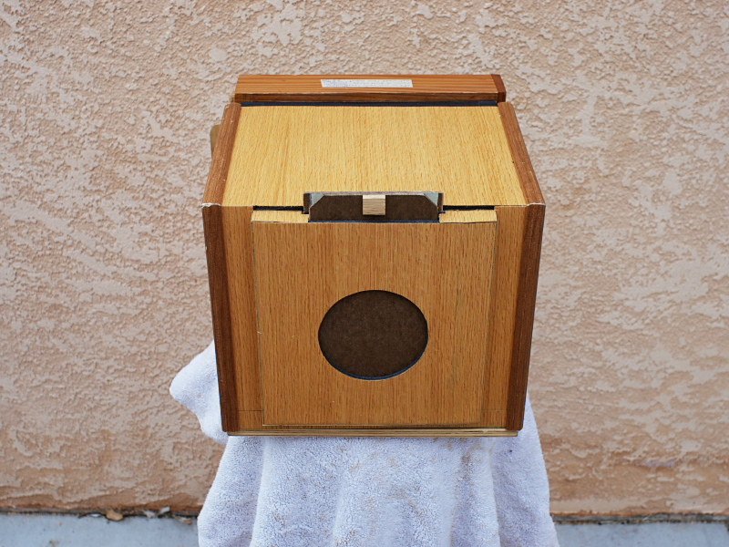
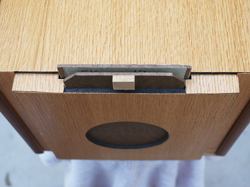
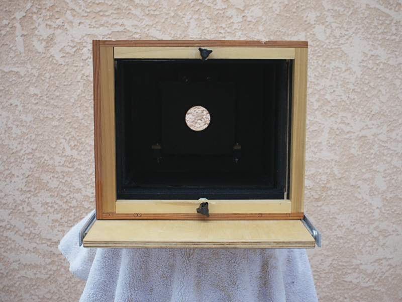
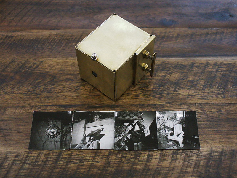
video for my You Tube channel, within which I made mention of, and demonstrated, a small, brass pinhole box camera, designed to make small images onto two inch square pieces of photo paper or film, taped to little brass film plates that fit into the camera via a changing bag. A humble little camera, it had seen much use about a decade ago, and promised much more, but since then has been relegated to the storage bin, acquiring the patina of disuse. Alas, such is life, so full of opportunities missed or squandered.

But then something curious happened. One of my video's viewers had recently contacted me, inquiring about possibly purchasing a copy of said camera. Thinking it over for a day or two, I finally decided that, rather than try to recreate a one-off camera design, why not just sell this very same camera? After all, it wasn't getting much use any more, being stowed away for all of these years, its last use only a distant memory in the back of my mind. I had recently been thinking about what to do with this sizable collection of pinhole cameras I've assembled over the years, that are no longer getting regular use, thinking of perhaps giving them away to some local school's darkroom program, if they'd have them, but never made any progress on the idea. In this newfound opportunity, I sensed that perhaps something better could come of it than what I would ever have accomplished on my own; the person wanting to buy it is a graduate photography student and aspiring artist, and so I am flattered to see this little gem of handiwork get a second lease on life in the hands of someone much more creative than myself.

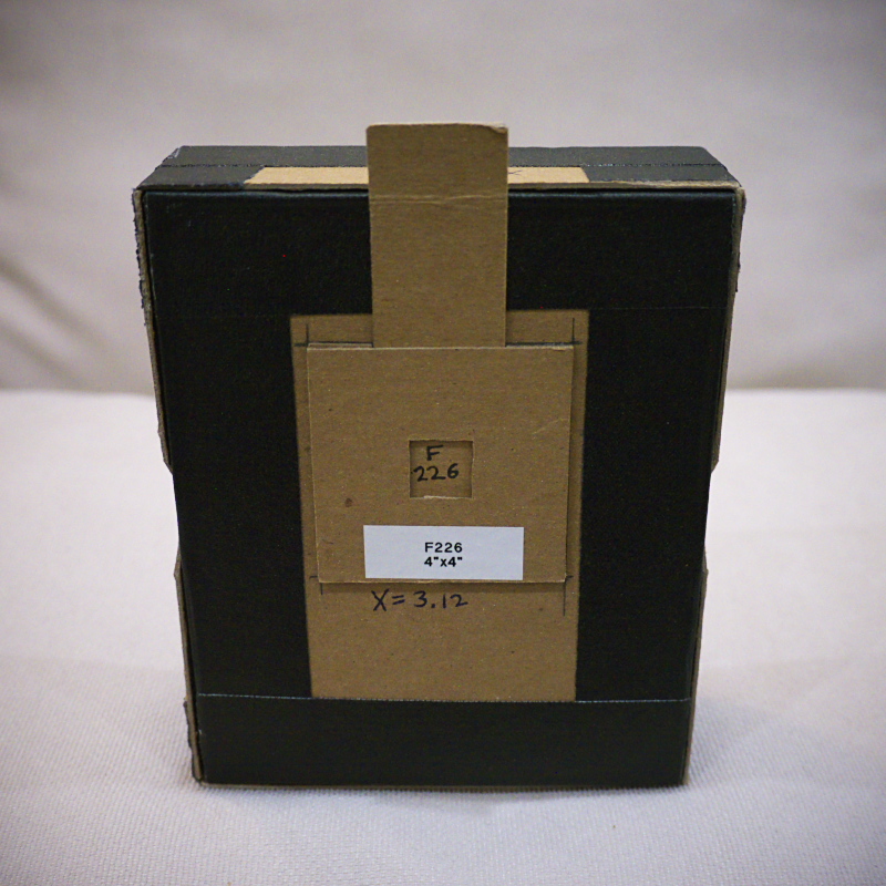
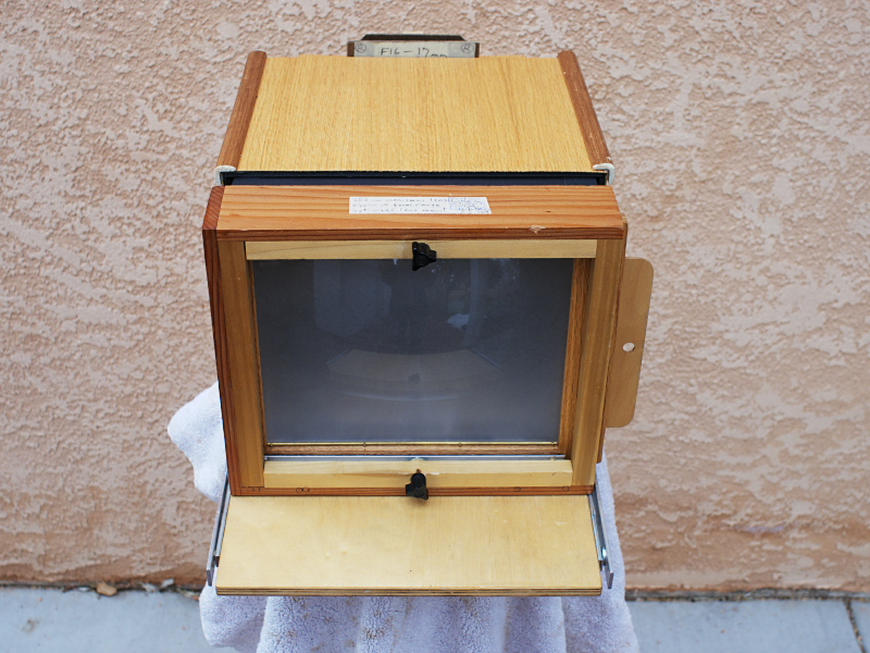
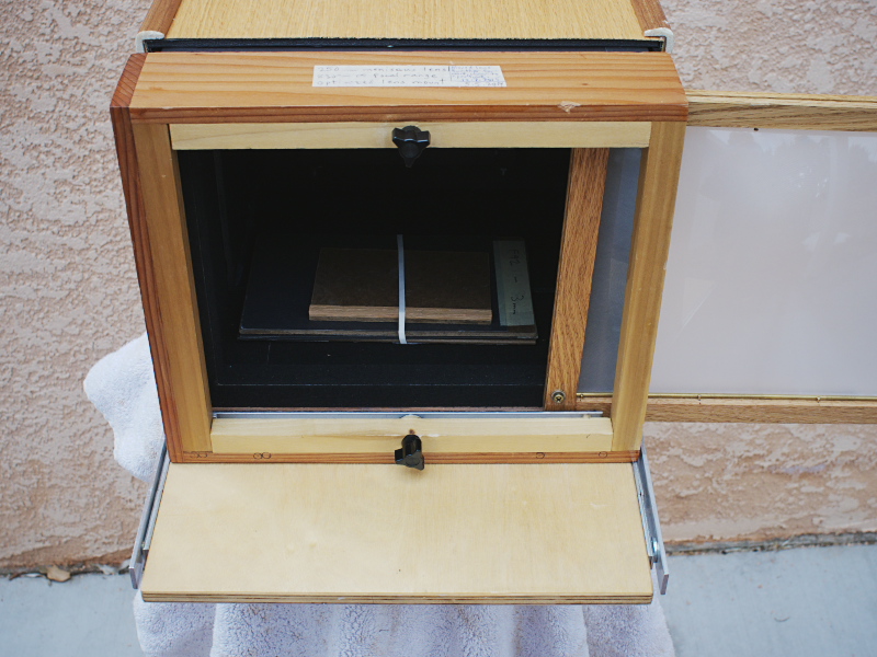
But first I had to clean up the camera a bit, it being spotted and blotched from years of misuse; a thorough cleaning would prepare the brass surfaces for growing a fresh new patina, representing a true second lease on life. But also, I wanted to test out the camera a bit, to make certain that it indeed still worked as advertised, and also for the opportunity to include a few sample images along with the camera when I shipped it; I had never before used it with Harman Direct Positive Paper, and was anxious to try it out. I also wanted to experience working with it one last time.

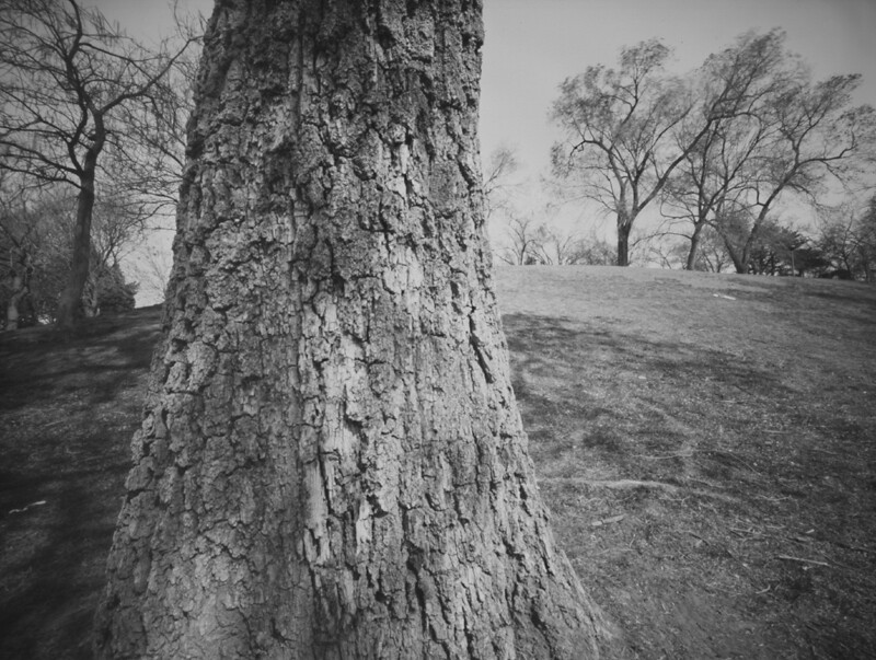
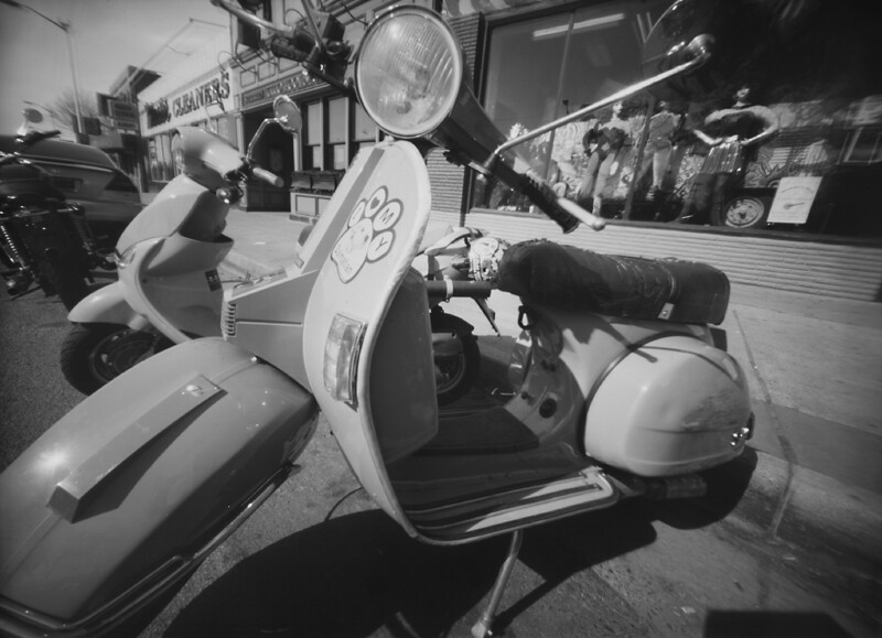
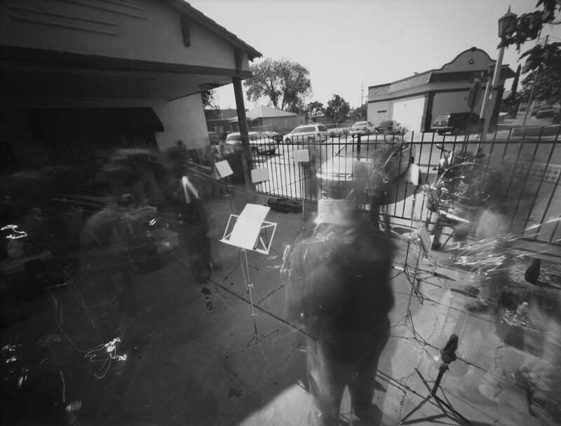
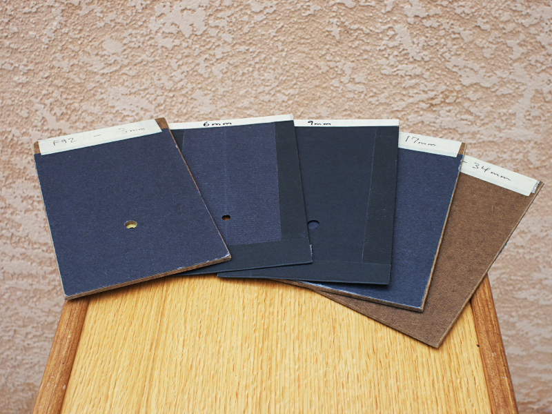
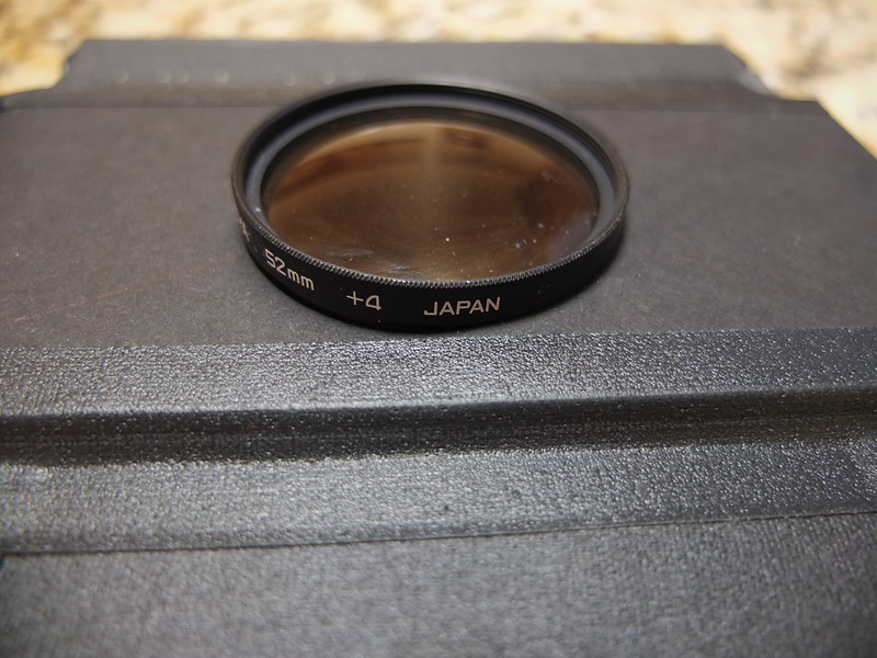
In deciding to make these test images using the Harman paper, I was reminded that normally I wouldn't use this paper in a pinhole camera, due to its extremely slow speed in cameras whose focal-ratios might be well into the hundreds, which in my past experience has required extended exposure times, even in bright sun, of well over a minute or two. But this little camera has a focal ratio of only F/140, sufficiently fast to permit an exposure time of only 15 seconds or so in bright winter's daylight.

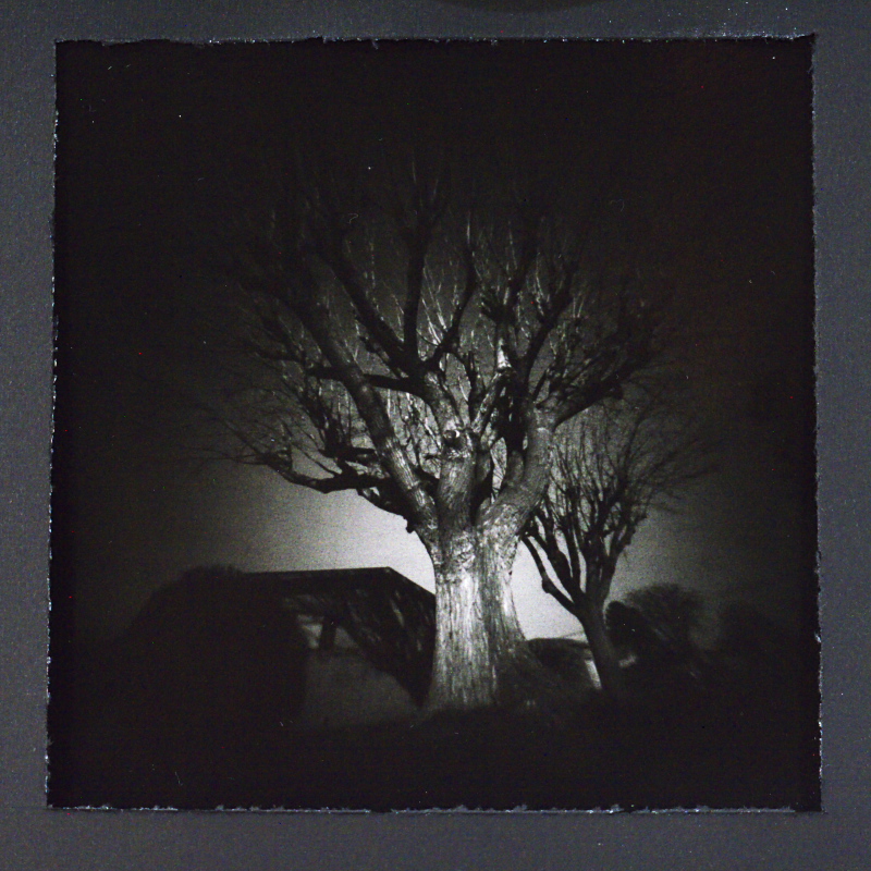
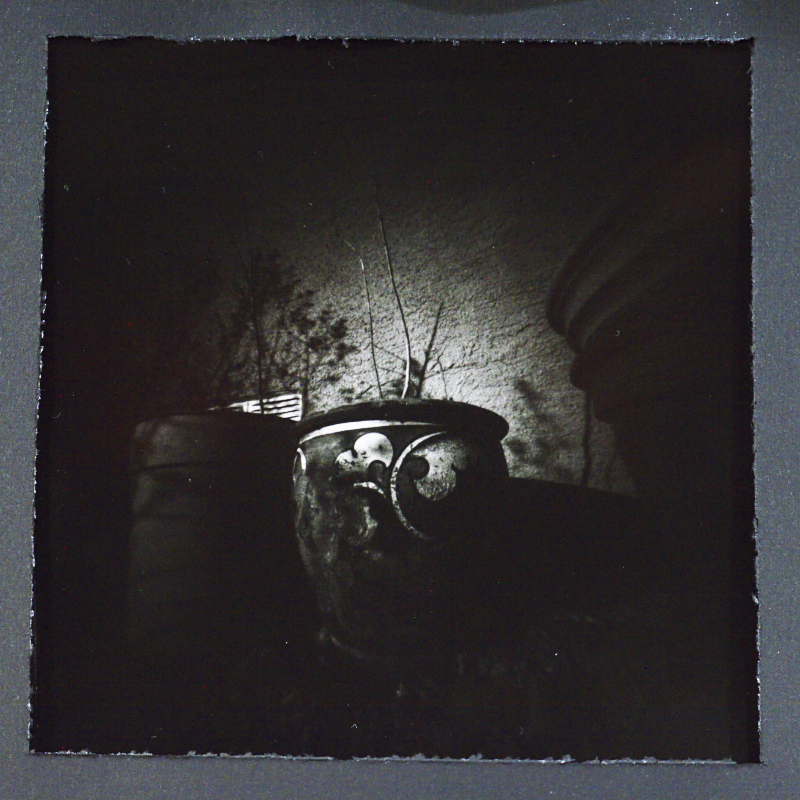
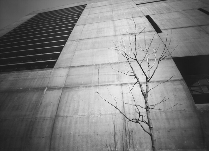
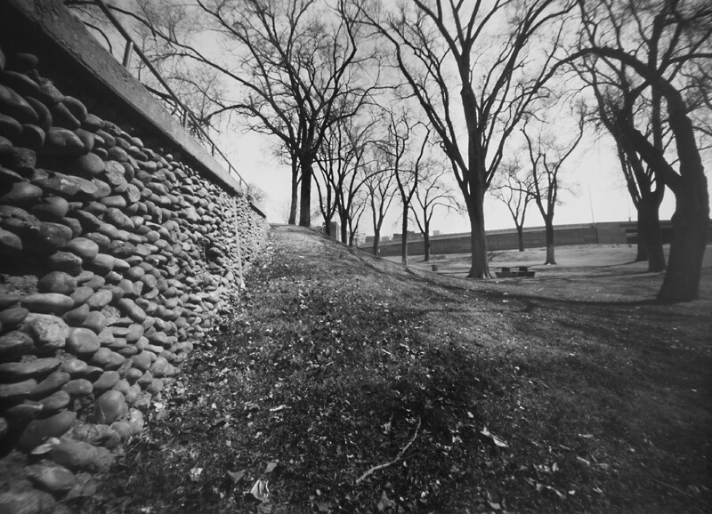
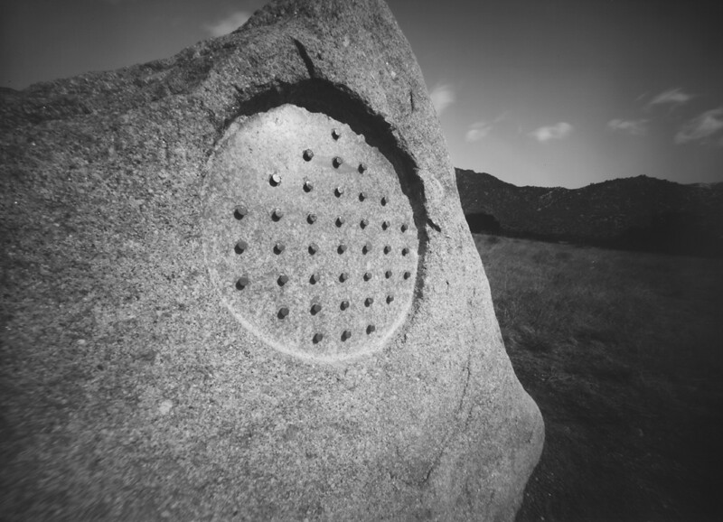
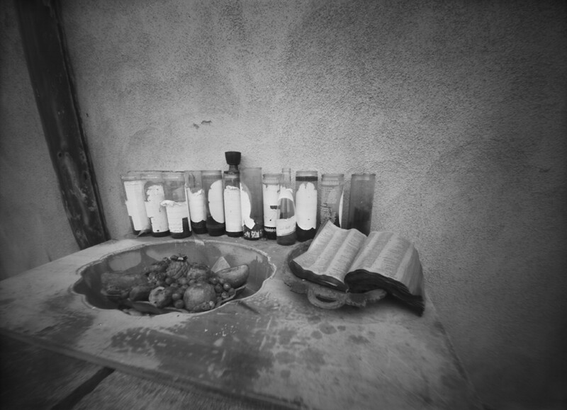
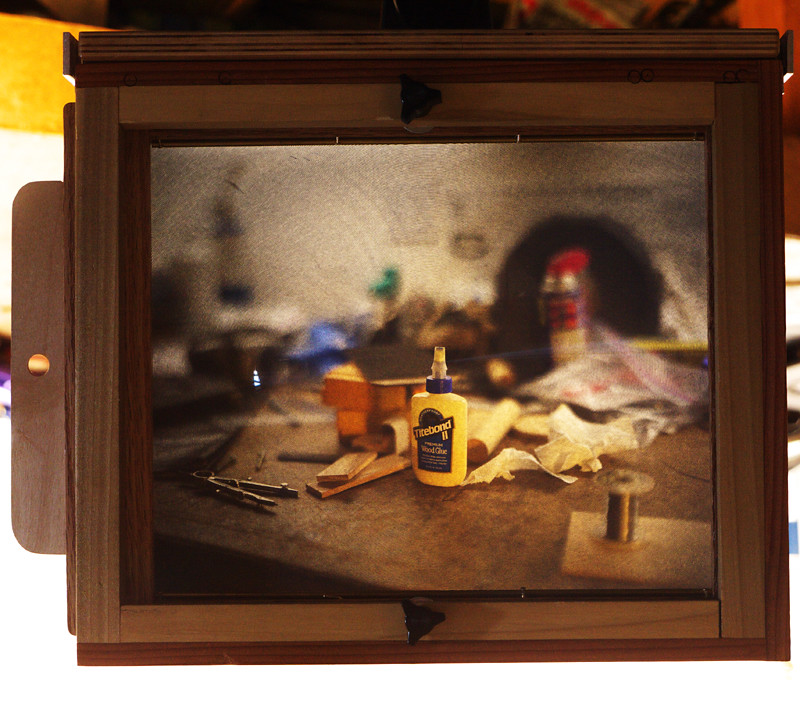
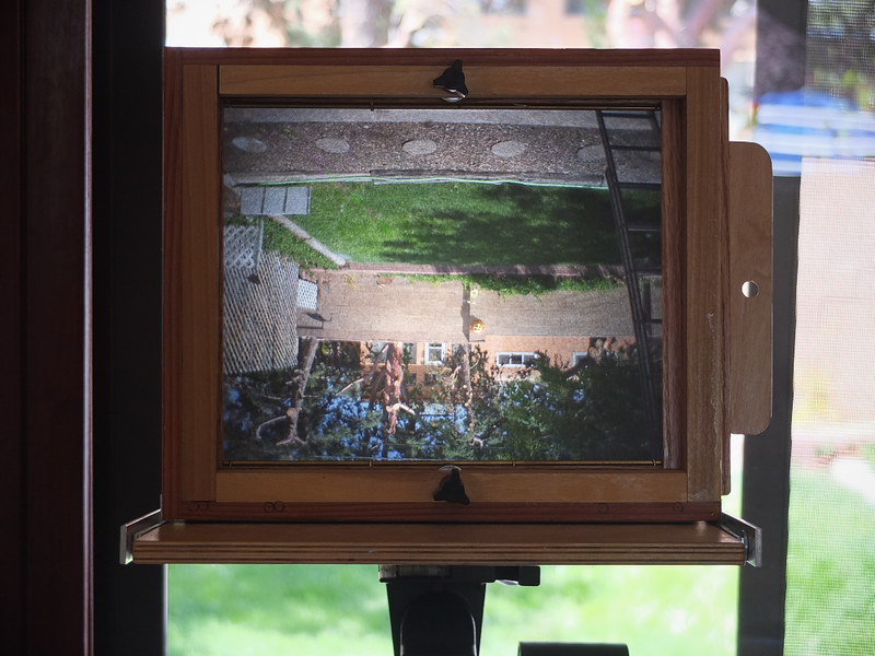
The resulting prints startled me in their quality, I must admit. No, I don't really have seller's remorse; I'm happy to see this camera go to a better home, where it will, at long last, see its purpose in life fulfilled. But in the process of letting go of it, I had gleaned a newfound appreciation for how beautiful a small, well-crafted direct positive pinhole print can be. These images are small, certainly, but also sharp - startlingly so; enough so that one would be hard pressed to tell that they had been exposed in a pinhole camera at all.

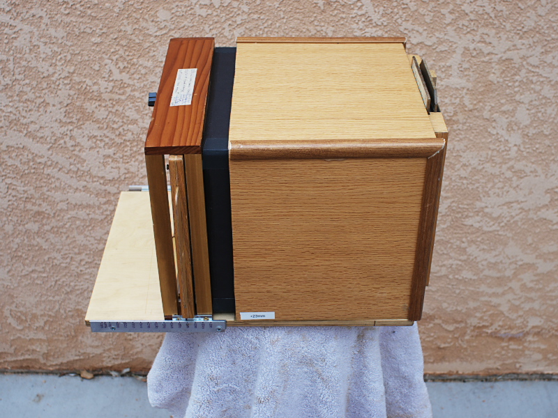
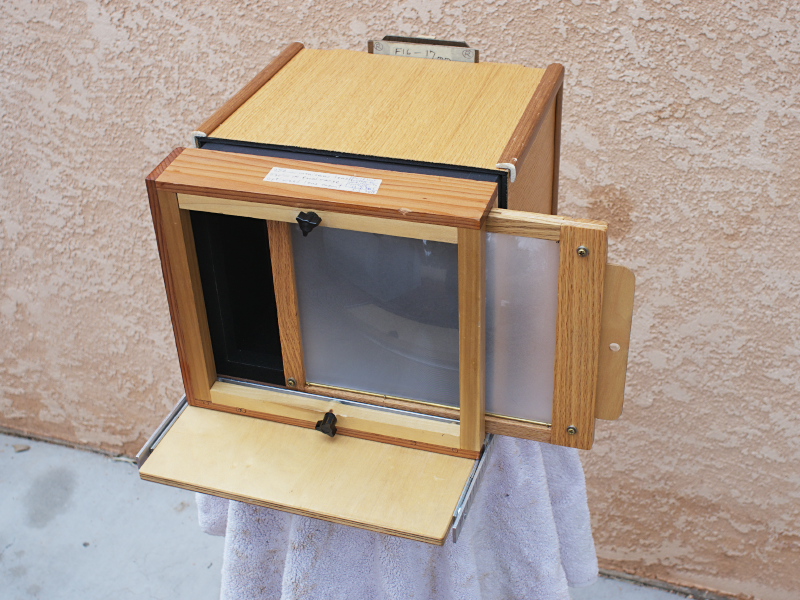
This last week I've been preparing the camera for shipment to its new owner, including making a wooden base upon which the camera can be mounted securely to a tripod, and through this process I began thinking deeper about these pristine little prints produced by this humble brass box, thinking that perhaps I need to dig out of the storage bin another small-format pinhole camera (or, dare I say it, make yet another?) and try my hand again at more of these diminutive direct positive prints. There's something intimate and personally familiar about these small, 2" square images; they don't cry out for attention with some ostentatious artistic pretension, like mural-sized prints in today's photographic galleries might; they're smaller than what one might view on one's own smartphone, even. You hold them in your hand, nestled in your palm ever so delicately, like a dried leaf or dead insect, and peer into them in wonder, like artefacts of some lost archaic process, up front and held close to one's self. They're small enough that you have to expend some effort in comprehension, but not so small that you need a magnifying glass.

I can see displaying these little prints matted to an oversized frame maybe eight or ten inches square, big enough to isolate them from their surroundings, to give each one the space they might need to breathe their own life and find their own context, with the help of the viewer's participation.

By the end of this week, this little camera will be forever out of my hands, hopefully in better charge of someone more intent on photographic creation than I; but what I've gained in exchange is a newfound appreciation for the power of small, pristine quality pinhole prints, and for that I'm grateful, considering myself richer for it.

A technical side note might be in order, pertaining to how I develop these little prints. Yes, one could easily do so in open trays in one's darkroom. But my darkroom these days is chilled by winter's cold, being located in an unheated garage, and so I prefer the convenience of using a developing tank in the comfort of my warm kitchen.

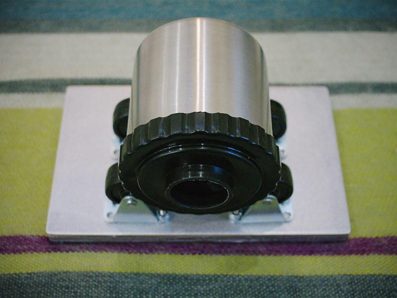
Those of you who've seen my You Tube videos might know how I do this, but for these small prints it involves taking a small metal 35mm developing tank and adapting it for use as a makeshift rotary processor. For one or two prints, I will keep the metal reels inside the tank and insert the paper, emulsion side facing inward, in the gap between the outer edge of the reels and the inside surface of the tank. Two such prints can be thus positioned, opposite each other so any potential movement won't cause them to overlap and interfere with their processing.

For three or four prints at once, I will remove the reels and apply little loops of painter's masking tape to the inner side wall of the tank, which will hold the prints into position, evenly spaced for processing.

Only 110 milliliters of chemistry are required for processing; I will typically use Ilford Multigrade or PQ paper developer concentrate, diluted "1+10," meaning 10mL of concentrate into 100mL of water. Once the prints are mounted in the tank and the lid installed (requiring a changing bag or darkroom), the chemistry is poured in through the lid of the tank, which is then positioned on its side and gently but continuously rotated for the duration of the processing time. This particular volume of chemistry is more than adequate to process four prints at once, while being insufficient to cause the liquid to slosh out of the lid while being oriented sideways and rotated. In a rotary process, instead of the tank being completely filled with chemistry, as you would with roll film, you only need this small volume, enough to just periodically submerge the paper as the tank is continuously rotated.

It helps to have a roller base upon which to spin the tank; while automated systems can cost thousands of dollars, and you can purchase a manual Jobo roller base for upwards of $50 or more, it's possible to make such a manually-operated base yourself, using parts readily available from the hardware store, which I'll cover in a subsequent article and/or video. But even without a roller base, you can simply lay the tank on its side and slowly rotate it on your kitchen countertop; use a cutting board or other thin piece to elevate the body of the tank far enough above the work surface so that the lid of the tank overhangs the edge of the board, with the opening pointed over the edge of the sink in case of spills, permitting it to rotate easily, while remaining level. Also, a terry cloth or similar dish rag on the cutting board can often help the tank rotate easier.

I have three such stainless developing tanks, and have noticed that two of them leak slightly from the edge of the lid when placed on their sides and rotated, and so I only use the third tank as my dedicated mini-rotary processor; if yours leaks, just take the necessary precautions.

I should mention, when working with fiber-based print paper such as Harman Direct Positive, of the need to adequately rinse the paper after processing, in order for it to be considered archival; otherwise the fixer chemicals will remain within the paper fibers and, over time, degrade the paper; because of their plastic coating, RC papers have less of an issue with this, but Harman Direct Positive only comes in a fiber paper version. For this reason it is advisable to use a rinse aid after the fixer and initial rinse, to help shorten this required archival rinsing time and conserve water.

After the final rinse, the paper needs to be squeegeed off so its front and back surfaces are just damp, then use a hair dryer to dry those surfaces; the inner paper will still be wet, however, and thus the paper will need to be thoroughly dried. When doing so, fiber-based paper has a tendency to severely curl toward the front side of the paper, due to emulsion shrinkage. To prevent such curl I will, after squeegeeing and blow drying, tape the prints face-up to a sheet of glass, using drafting or artists tape along the very edges, then place it in a warm, clean area for several hours. Periodically check on the paper and, if needed, reattach the tape if it starts to peel up from the glass due to the paper's curling. If done properly, you can get fiber prints to dry very flat using this method, without the added expense and bulk of a dedicated print drying machine. Making do and improvising is the secret to success with these legacy processes.

It's difficult to adequately describe the joy I experience when I open up the developing tank after one of these short 10-minute processing sessions and behold these pristine little gems still wet in my hand. It's something about their diminutive size and unexpectedly sharp appearance that gets me every time. I invite you to experience the joy of pinhole photography for yourself, the rediscovery of new beginnings.

Sunday, January 17, 2016

Photo Storage Box Pinhole Cameras


I've covered in past articles a number of different box camera designs, and today I'd like to discuss making pinhole cameras from photo storage boxes. As background, there are times when I've built pinhole cameras entirely from scratch, while other times I will notice a box or container in a store with some feature that presents itself as being a likely candidate for conversion into a pinhole camera.

Craft stores are a likely place to find such boxes, and one of the most common and least expensive are these cardboard storage boxes for photos and videos. These come in a variety of colors and surface finishes, but the ones that initially piqued my interest were finished in black felt, including along the inside edge of the lid, implying that they came already light-tight.

Some years ago, out of curiosity, I purchased one of these boxes in order to experiment with it, with the thinking that if it didn't work out as a camera then I could always use it for its original intended purpose, as storage. The first thing I noticed was that, although on its long side it could fit an 8" x 10" sheet of photo paper, it was too narrow on its short side; unless the paper were curved to fit, or trimmed to size.

Once converted to a camera, I initially made some test shots with the paper mounted curved inside the box, but movement of the paper while the camera was pointed downward caused some of the corners to be blurry, and so I subsequently converted it to hold the sheet of paper, trimmed to fit, instead flat against the inside of the box, using a cardboard holder piece, with gaffer tape handles for easy removal.

While deciding how to convert the box to a camera, I had to decide how best to orient the paper relative to the lid. While it might be easier to insert and remove photo paper into the shallow lid of the box, having the film located there would mean a higher chance of it being fogged by light-leaks from the nearby lid opening. Therefore I instead located the film into the bottom of the box; light leaking inward from around the lid would have to reflect off the inside surface of the lid and then into the box, before it could fog the paper; spray painting the inside surfaces flat black considerably reduced the possibility of such reflections.

So the pinhole and shutter are located in the lid of the box. A square hole is cut in the lid, lined with gaffer tape and the brass pinhole plate mounted over the hole, from the inside, with more tape. The shutter is a thin piece of masonite board that pivots on a screw - easy enough that anyone can make one.

Mounting the box to a tripod required a bit of thought. Since these boxes are essentially thin cardboard, they're too flimsy to directly install a 1/4-20 tripod bushing. Instead, I made a heavy plywood mounting plate with tripod bushing, to be mounted atop a tripod, big enough for the box to easily sit upon, and equipped with screw eyes for the attachment of bungee cords, that serve to hold the box securely upon the platform while allowing easy removal when needed.

This first photo storage box camera ended up being enough of a success that I went and bought a second identical box and made another camera, this one having a focal ratio of F/300, a bit sharper than the F/275 of the first.

In practice, I trim, pre-flash and load the paper negatives into both cameras while in the darkroom, then carry them around in one of those reusable shopping bags, along with a tripod, mounting plate and light meter. But that only gives me the possibility of two images, unless I also bring a changing bag and box of additional sheets of photo paper.

Because of this limitation, I later began thinking of ways to provide for more images while out and about with such a camera. One idea is to simply carry more one-shot boxes; but this can be ungainly and impractical. Another idea is to have a shallow compartment behind the film plane where several additional sheets of paper can be stored, to be swapped out within a changing bag. Though this would work, it also makes the focal length of the box even shorter, the angle of view even more severely wide. Although I could have then extended the focal length by moving the pinhole/shutter further from the paper, with the addition of an extension box atop the lid, in the end I decided on a different configuration entirely.

Instead of the near 8" x 10" image size, I decided that 5" x 7" would be a sufficiently large format while permitting the installation of a two-slot paper storage compartment inside the box. So I went back to the craft store and bought another photo storage box. Although I couldn't find the felt-covered boxes (they seemed to have been in stock for only a few seasons), I did find a box already colored flat black inside and out.

This new camera ended up being oriented vertically, with the storage compartment in the bottom half, the camera chamber in the top and the lid along the front side. A heavy plywood mounting plate, with tripod bushing, is permanently bolted to the bottom side of the box, providing for a stable support and low center of gravity.

The internal paper storage box is made from foam core board, cardboard and gaffer tape, and is installed in the camera such that its open end is oriented opposite the camera chamber, pointing down, to prevent stray pinhole light from fogging the paper stored within.

In use, the camera is removed from the tripod and zipped up inside a changing bag, then the elastic bands securing the lid are removed, along with the lid itself. The storage compartment is then flipped around so its slots are pointing up, and the paper changed out; there's enough capacity in the storage container for several hundred sheets of paper. A piece of cardboard is used as a bracket upon which the negative is mounted via a loop of drafting tape, providing for easy removal and installation.

The shutter and pinhole assembly are very similar to that of the other one-shot box design, mounted in the box lid but instead mounted off-center, so as to be located directly over the camera-chamber-half of the box.

I've made a video about these two kinds of photo storage box cameras; the embedded You Tube link is at the top of this article.

This is not the first storage-slot type of pinhole camera I've built; I believe the last four or five have employed this design, all requiring the use of a changing bag within which to swap out the paper between shots. While this method does indeed provide for a practically unlimited number of exposures, that practicality is offset by the inconvenience of having to, after every exposure, remove camera from tripod, zip up into changing bag, swap out paper, unzip from changing bag and remount to tripod. It also implies that some sort of makeshift seating area needs to be found every time.

One possible alternative that I keep kicking around is to build a light-tight arm sleeve into the back of a box camera, permitting the paper to be changed out while it remains mounted upon the tripod, needing only one hand to operate; but that's a project for another day.

Post-script: A sampling of images created with both the F/275 and F/300 one-shot photo storage box pinhole cameras, using pre-flashed grade 2 RC paper negatives.

PhotoBox_300_005aa
PhotoBox_300_004aa
PhotoBox_300_003aa
PhotoBox_300_002aa
PhotoBox_300_001aa
PhotoBox_275_004aa
PhotoBox_275_002aa
PhotoBox_300_006aa

Tuesday, January 12, 2016

Shutter Speed Tester

P1110597a
Schematic001
One of the previous You Tube videos I posted made reference to using an electronic circuit and oscilloscope for measuring the shutter speed of my 8" x 10" box camera's mechanical shutter. Since then I've been asked to provide more information on this circuit.

As can be seen above, the little circuit board has a handful of components, the most important being an optical sensor, salvaged some years ago from a VCR. This particular component has no identifying part number, and so I cannot give you any more information about sourcing a similar part, but a description might be helpful. It has four legs and two sections, an infrared-emitting diode section and an IR-sensitive photo-transistor section. In the schematic diagram I've drawn S1 as it appears when looking down at the sensor end of the device, with the four legs spread out underneath. It was originally used underneath the supply and take-up reel spindles in a VCR to sense rotation of the spindles. IR light emitted by the device would be reflected off a series of silver and black segments on the underside of a reel spindle, resulting in a square-wave output signal from the photo-transistor as the spindle rotates. The device is intended to be powered from a 5v TTL source.

The circuit is powered by a standard 9V battery, regulated down to just under 5v by means of resistor R1 and zener diode D1. Keep in mind that this circuit was made from spare parts I had on hand, so it's not optimized in design. In particular, the value of R1 (here 150 ohms) is determined by how much current is drawn by the photo-transistor device S1, and the zener diode. The lower the value of R1, the more wattage diode D1 will consume in trying to regulate the voltage to about 5 volts, thus determining how much wattage the diode needs to be rated at. I have the sense that I could have increased the value of R1 and used a lower wattage diode. If you decide to build something like this, you'll have to measure the current flowing out of R1 and calculate its optimal value accordingly. As it is, none of the parts draw enough power to get too hot, so at least I'm in the ballpark, design-wise.

Resistor R2 provides bias voltage for the photo-transistor portion of device S1. The red LED diode, D2, that's in parallel with R2, was added as a means of improving the biasing of S1; without D2, the device doesn't output as much of a signal.

The right-hand portion of S1 in the diagram is the IR-emitting diode, which is not needed in our application, so its power leg is left open.

In actual use, this circuit is intended to be used with an oscilloscope, on whose screen you can measure the pulse width resulting from the shutter firing and thereby calculate its speed. I also connect a volt meter across the output, as a way of verifying the output switches from its no-light condition of around 4.2 volts to below 1 volt when the sensor is hit with a bright source of infrared light. I connect the ground leads of both the meter and scope to "gnd," and the positive lead of the meter and scope probe to "out." A standard 9V battery is connected to power the circuit.

To calculate the shutter speed, measure on the scope the pulse width in graticule divisions (you might have to fiddle with triggering settings on your scope to get it to properly display when the shutter is fired), then multiply the number of divisions by the setting of the time base control. This tells you how many milliseconds the shutter is opened. To convert that into a practical fractional value usable with a light meter, take the pulse width in milliseconds and divide by 1000; then invert the result - this will be the fractional value of the shutter speed in seconds.

Example 1: the pulse width measures 125 milliseconds on the scope. 1/(125/1000) = 8. So your shutter speed is 1/8 second.

Example 2: the pulse width measures 112 milliseconds on the scope. 1/(112/1000) = 8.93. So your shutter speed is 1/8.93 seconds. You can see how representing the shutter speed as a fraction helps to determine the correct aperture required on your light meter, since I know of no meter that reads shutter speed in milliseconds of duration (at least my analog meters don't).

Since the sensor S1 is only infrared-sensitive, you'll have to use a bright source of IR light. I found a halogen flood lamp, at least 65 watts, will work well. You may have to adjust the angle of the light striking the sensor to optimize the output signal to be as low as possible when lit; that's what I use the meter for, prior to actually firing the shutter and using the scope.

I plan on installing this circuit into a housing, and adding a switch and output terminals, so the battery can be kept connected; this will make it more functional and practical.

I know there are other shutter speed testers that use a microphone and audio-editing software to measure the time duration of the sound made by the shutter. While this method might be accurate enough for curtain shutters found on film cameras, a shutter like mine doesn't make a distinctive enough start and stop sound to make audio measurements accurate. I have the sense that the same is true with any kind of leaf shutter. So an optical means of measuring shutter speed should be more accurate.

Let me know in the comments section below how your shutter speed tester project comes out.

Thursday, December 31, 2015

Mechanical Shutter Experiments


Earlier this week I created another photography video, this time about the experimental shutter I built, some years ago, for the 8" x 10" box camera.

The genesis of this project was having used paper negatives in improvised lens cameras and finding that, due to the speed of the paper (I rate Freestyle Photo's Arista grade 2 RC paper at an exposure index of 12), I'd have to stop down the lens to a very small (2-3mm) aperture, in order to make the shutter speed long enough (>1 second) to accurately and repeatedly time by a hand-operated shutter, in bright daylight landscape conditions.

Under dimmer kinds of light, like window light, I've made a number of satisfying indoor still-life exposures in the daytime, where these improvised lenses, operating at wider apertures, display some interesting optical effects that make the resulting images rather special. But under bright daylight they have to be stopped down so much, in order for their exposures to be timed by hand, that they come to resemble hybrid pinhole/lens optics, lacking those optical aberrations I've come to appreciate from adapted optics, like binocular objectives and meniscus lenses.

So it seemed that I'd need some kind of shutter mechanism. But how?

I spent a long time cogitating about simple mechanical shutters, and ended up making a series of proof-of-concept sketches over several years, trying to find some design that might prove workable. In the end, I felt that I just had to start building something, and so it became a design-as-you-build kind of project, using scrap bits of hardware I'd collected over the years; my motto being something along the lines of never throw anything away, you might use it someday.

What I was trying for was a shutter whose speed could be varied over some practical speed range, to account for differences in exposure. Many of the early designs I considered were simple slit shutters, operated by spring tension and moving either horizontally or vertically, with the width of the slit accounting for the variation in exposure. But I soon realized that with a fixed spring tension a variable slit shutter operating up front at the lens would only yield a small range of speed variations.

After some time I realized that I could make the traveling slit camera into a rotary blade camera, and by altering the angle between the blades the timing could be adjusted. However, my initial idea was much more grand: by slowing down the speed of rotation, I could have a wider range of speeds, from multi-seconds long to fractions of a second, perfect for paper negative media.

P1080490a
But I never got far enough along with this design to build a practical mechanism for slowing down the rotation while making its speed reliable and repeatable. The one big idea I had for this was based on a mechanism I'd seen years earlier, while repairing a Technics audio cassette deck, which was the method used to dampen the speed of the cassette door when it was ejected. Most cassette players used a simple plastic dash-pot mechanism, a piston and cylinder, with an o-ring and some grease, so that as the spring tension tries to slam the door open, the air in the piston is released in a controlled fashion through a small opening, allowing instead the door to slowly and smoothly open. The problem with this design is when the grease hardens up over time, and the cassette door slams open uncontrollably.

Panasonic's method was different. They used a small brass whirligig, a 4-vane rotating piece that was driven to rotate by a drawstring band attached to the door mechanism. As the spring tries to forcefully slam open the door, the band rapidly spins the whirligig, the resulting air pressure slowing down and regulating the speed of the door into a smooth motion. The best part of this design was its reliability, as there were no lubricants to harden over the years.

So my idea for the shutter was to employ this whirligig mechanism, in a small but rapidly turning pulley with vanes, that the shutter cord would spin as the shutter was moving, helping to keep the speed constant. In theory, it sounds plausible; but I never got to the point of implementing it with this shutter.

As you note from the video, the problem with this shutter is that the three speed adjustments, that alter the angle between the blades, don't really offer much variation in speed; and there's too much friction in the mechanism, caused by the way I designed for compensating for light leaks.

The sad thing about this project is that it's sat dormant for some years, as I just couldn't find the motivation to get back to improving it. But now, with these You Tube videos and this blog, perhaps I've painted myself into a corner whereby now I'm forcing myself to get back and finish these projects. And that's a good thing.

Here is a detailed photo of the shutter with the parts labelled, made a few years back; note that I've more recently changed the draw cord from a thin black to thick white cord.

P1080477b
This video was the first of two parts; next week I hope to take the camera out, with shutter attached, and make some usable images. Stay tuned.

Wednesday, December 23, 2015

Improvised Camera Building - 8 x 10 Tailboard Box Camera

Sandias_8x10001a
"Sandia Mountains," Harman Direct Positive Paper in 8" x 10" tailboard camera

Though most of the handmade cameras I've fashioned have been of the pinhole variety, years ago I began experimenting with what could be termed "improvised optics," at first using the objective lens from a 7x50 binocular, which projected an image circle big enough to cover a 5" x 7" film format, though I usually employed it in my 4" x 5" Speed Graphic camera - mainly because of the convenience offered by the camera's curtain shutter.

Eventually, the time came when I wanted to try my hand at building an 8" x 10" camera, mainly because of my preference for working with paper negatives, which can easily be contact printed to good effect, and wanting to work in larger sized images, encouraged by the low cost of large format photo paper as compared to sheet film.

But I was never attracted to the ability of a large format bellows camera to twist itself, pretzel-like, into all kinds of contortions, as is the tradition of architectural and product photography where geometry correction or manipulating the plane of focus might be important. I'm more of a documentary photographer in the tradition of the 19th century forefathers, and thus a simple box camera was more to my liking, but one that could be easily focused.

P1110259a
And thus I came up with the notion of a nested box tailboard camera, so-called because of the rear half of the camera that slides in and out of the front half for focusing, resting upon a baseplate for support. I had been inspired by images of historic cameras seen at the George Eastman House online museum, and figured I could cobble together something functional, if not visually appealing.

P1110265a
So I found a sturdy, flat wooden board as the basis for the camera, and built upon it a foam core front box structure, that houses the shutter slot and aperture plates. The foam core board surfaces are covered with thin countertop laminate that provides a faux wood-like appearance, while the edges are reinforced by wood-printed foam trim molding.

P1110261a
The rear, sliding half of the box is built around a frame made from scrap wood that provides a slot to insert a film holder or view screen frame, which is attached to the rear of the foam core box that slides snuggly in and out of the front half. What provides the light-tight seal between front and rear halves of the box is due to the interior of the camera being flocked with adhesive black craft felt, and that light leaking inward through the gap between box halves has to travel up to the front of the box, then reflect back toward the film plane, in order to fog the film. This is due to the rear half sliding inside the front half; had it been built the other way around, light could easily leak in between box halves and directly hit the edges of the film holder.

Though the camera initially lacked a mechanical shutter, I figured with the slowness of paper negatives and a small enough aperture stop, exposure times could be long enough (>=1 second) as to be accurately timed by hand with a simple guillotine-style shutter.

The length of the camera was initially designed around a meniscus lens salvaged from an industrial semiconductor stepper machine (think of it as a reverse enlarger: a reducer; and made by Nikon), that was mounted to the inside of the front of the box via a bracket and bolts that made it easy to remove and replace with other lenses.

P1110264a
The opening in the front of the box provides for a clear aperture of 2 inches, but meniscus optics are rarely very sharp operated that wide, and so to aid in focusing I made an aperture plate stopped down to 17mm, which clears up the view of these single-element lenses sufficiently to enable a distinctly clear image while still being adequately bright. Unless sunlight is directly striking the view screen, I can often make out a distinct image without the aid of a dark cloth.

P1110267a
I also made a number of other aperture plates, the smallest being 3mm, that cuts the light down sufficiently to permit hand-timed exposures in bright sunlight. Some of these plates are cut from masonite board, while others are fashioned from sturdy black craft paper. In the case of these latter plates, their edges are reinforced with black gaffers tape and when inserted into the camera the excess slop in the aperture slot is filled in with a masonite spacer.

P1110260a
I had fashioned a focal length scale along the lower right edge of the camera, initially calibrated for this first meniscus lens, that enables the camera's working aperture to easily be determined, by dividing focal length by aperture diameter. This method automatically compensates for any "bellows extension factor" caused by close-focusing. Additional lenses are used with an offset number that's added to or subtracted from the scale reading, depending on the lens.

I did experiment with the 7x50 binocular lens, mentioned earlier, that actually makes a very nice 8" x 10" image, with just a bit of vignetting, but its focal length (150mm) is too short, and the box halves too long, to permit that lens to be focused at infinity. However, with the box halves pushed together as close as they will go, that lens operates as a close-up lens for tabletop dioramas and still-life scenes.

P1080878
P1080865
Another lens I acquired with the intention of using in this camera was a multi-element lens cell from a Xerox copy machine; however, such optical designs cannot be used with external aperture stops without severe vignetting, which I only discovered after purchase of the lens. Yes, it does operate nicely wide open, but the resulting image is too bright for an exposure to be made with a hand-time guillotine shutter. That lens was later repurposed in my Speed Graphic (since it has its own focal plane shutter), using a special bracket I constructed for the heavy lens, which reminds me somewhat of a Kodak Aero Ektar.

DSCF1660a
So, I used this camera, on and off, during the last few years with the single element meniscus lens, but wasn't entirely satisfied with the image quality. Then last year I was given a close-up lens, intended to be threaded over the front of a 35mm SLR lens, and found its 275mm focal length and optical quality to be ideal for this camera. This has now been the standard lens I use, of pretty good quality when stopped down, as was done with the top image, taken in far northeast Albuquerque near the Sandia Mountains, exposed onto Harman Direct Positive Paper (which is why the image appears reversed, for those of you familiar with this terrain).

P1110262a
P1110263a
DSCF1655a
I would be remiss not to describe the view screen itself. Rather than employ a built-in view screen with spring hinges, as is the case with conventional large format cameras, I built a laminated wooden frame that slides into the side of the camera, just like a sheet film holder. The viewing screen is a plastic fresnel magnifier, purchased from a local office supply store, whose smooth side (facing toward the lens) was sanded down with 600 grit emory using a random orbital sander, offering a surface of sufficient quality for composing an image, while the rear fresnel ridges help to focus the image direct rearward, making for a brighter image.

I built the wooden frame such that the distance from the front of the frame to the front of the screen is (nearly) the same as from the front of a sheet film holder to the film plane.

The camera is not nearly as heavy as it looks, due to its construction of layered foam core and countertop laminate, but the biggest challenge in carrying it in the field is its bulk. I've rigged up a makeshift camera strap to help carry its weight, which has helped.

P1110268a
I like that the interior of the camera serves as a storage compartment for spare aperture plates, and that it's rather weather resistant. There are times when I dream of building another version, a bit shorter, enabling me to use that binocular lens, but I have not yet done so. This camera has served as a real workhorse for experimenting with adapted optics as makeshift camera lenses, and is a real hoot to use.

P1080492a
One feature I have not mentioned is that I eventually made my own mechanical shutter, that fits over the front of the box, but that's a subject for another day.