Showing posts with label tailboard camera. Show all posts

Tuesday, January 12, 2016

Shutter Speed Tester

P1110597a
Schematic001
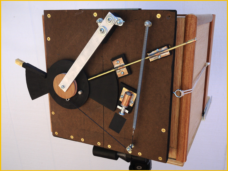
One of the previous You Tube videos I posted made reference to using an electronic circuit and oscilloscope for measuring the shutter speed of my 8" x 10" box camera's mechanical shutter. Since then I've been asked to provide more information on this circuit.

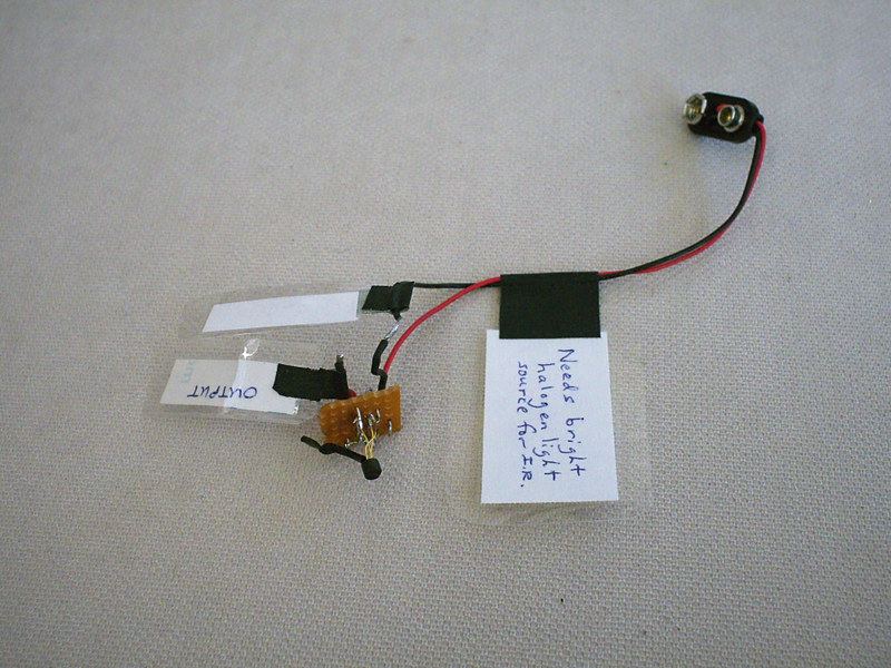
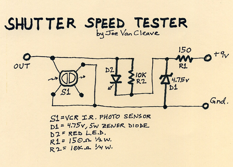
As can be seen above, the little circuit board has a handful of components, the most important being an optical sensor, salvaged some years ago from a VCR. This particular component has no identifying part number, and so I cannot give you any more information about sourcing a similar part, but a description might be helpful. It has four legs and two sections, an infrared-emitting diode section and an IR-sensitive photo-transistor section. In the schematic diagram I've drawn S1 as it appears when looking down at the sensor end of the device, with the four legs spread out underneath. It was originally used underneath the supply and take-up reel spindles in a VCR to sense rotation of the spindles. IR light emitted by the device would be reflected off a series of silver and black segments on the underside of a reel spindle, resulting in a square-wave output signal from the photo-transistor as the spindle rotates. The device is intended to be powered from a 5v TTL source.

The circuit is powered by a standard 9V battery, regulated down to just under 5v by means of resistor R1 and zener diode D1. Keep in mind that this circuit was made from spare parts I had on hand, so it's not optimized in design. In particular, the value of R1 (here 150 ohms) is determined by how much current is drawn by the photo-transistor device S1, and the zener diode. The lower the value of R1, the more wattage diode D1 will consume in trying to regulate the voltage to about 5 volts, thus determining how much wattage the diode needs to be rated at. I have the sense that I could have increased the value of R1 and used a lower wattage diode. If you decide to build something like this, you'll have to measure the current flowing out of R1 and calculate its optimal value accordingly. As it is, none of the parts draw enough power to get too hot, so at least I'm in the ballpark, design-wise.

Resistor R2 provides bias voltage for the photo-transistor portion of device S1. The red LED diode, D2, that's in parallel with R2, was added as a means of improving the biasing of S1; without D2, the device doesn't output as much of a signal.

The right-hand portion of S1 in the diagram is the IR-emitting diode, which is not needed in our application, so its power leg is left open.

In actual use, this circuit is intended to be used with an oscilloscope, on whose screen you can measure the pulse width resulting from the shutter firing and thereby calculate its speed. I also connect a volt meter across the output, as a way of verifying the output switches from its no-light condition of around 4.2 volts to below 1 volt when the sensor is hit with a bright source of infrared light. I connect the ground leads of both the meter and scope to "gnd," and the positive lead of the meter and scope probe to "out." A standard 9V battery is connected to power the circuit.

To calculate the shutter speed, measure on the scope the pulse width in graticule divisions (you might have to fiddle with triggering settings on your scope to get it to properly display when the shutter is fired), then multiply the number of divisions by the setting of the time base control. This tells you how many milliseconds the shutter is opened. To convert that into a practical fractional value usable with a light meter, take the pulse width in milliseconds and divide by 1000; then invert the result - this will be the fractional value of the shutter speed in seconds.

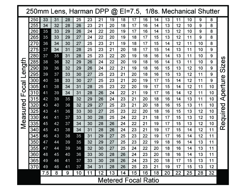
Example 1: the pulse width measures 125 milliseconds on the scope. 1/(125/1000) = 8. So your shutter speed is 1/8 second.

Example 2: the pulse width measures 112 milliseconds on the scope. 1/(112/1000) = 8.93. So your shutter speed is 1/8.93 seconds. You can see how representing the shutter speed as a fraction helps to determine the correct aperture required on your light meter, since I know of no meter that reads shutter speed in milliseconds of duration (at least my analog meters don't).

Since the sensor S1 is only infrared-sensitive, you'll have to use a bright source of IR light. I found a halogen flood lamp, at least 65 watts, will work well. You may have to adjust the angle of the light striking the sensor to optimize the output signal to be as low as possible when lit; that's what I use the meter for, prior to actually firing the shutter and using the scope.

I plan on installing this circuit into a housing, and adding a switch and output terminals, so the battery can be kept connected; this will make it more functional and practical.

I know there are other shutter speed testers that use a microphone and audio-editing software to measure the time duration of the sound made by the shutter. While this method might be accurate enough for curtain shutters found on film cameras, a shutter like mine doesn't make a distinctive enough start and stop sound to make audio measurements accurate. I have the sense that the same is true with any kind of leaf shutter. So an optical means of measuring shutter speed should be more accurate.

Let me know in the comments section below how your shutter speed tester project comes out.

Wednesday, January 6, 2016

More Mechanical Shutter Stuff


I was anxious to do some testing of the mechanical shutter for the 8" x 10" lens box camera, that I had wrote about in the previous article, but due to the cloudy, snowy weather this last week I didn't have enough light. The mechanical shutter has a speed of about 1/8 second; combined with the slow speed of the Harman Direct Positive paper (I rate it's Exposure Index at around 7.5), that means you need a relatively wide aperture to get sufficient exposure, or find bright daylight.

But last week I did have a chance to eke out one test, in my front courtyard, under a sky streaked with high clouds, barely enough light to get sufficient exposure, but the test did come out fine, indicating that my measurements of the paper's sensitivity and the shutter's speed were fairly close.

I was also anxious to complete part two of the video series about this shutter, initially hoping to find bright, sunny conditions where I could simultaneously shoot more tests while also recording some video. But the weather didn't cooperate, it remaining cloudy and stormy this week, and so yesterday I decided to just do a speaking video about the shutter, describing in detail how I control exposure using the choice of aperture plate, rather than actually demonstrating it live under real-world conditions.

In the course of preparing for this second video, I had to figure out in more detail how I was going to manage exposure control with this shutter. It finally struck me that, with a fixed, single speed, I'd be operating the camera as if it were set to "shutter speed priority" mode - you have one shutter speed, and the paper's sensitivity is also fixed. So the only control one has over exposure is choice of aperture plates. But I only had a handful of such plates made, a choice of 34mm, 17mm, 9mm, 6mm and 3mm. I had to figure out how many other apertures I'd need, and of what sizes.

Thinking further about this, I finally realized that there are two "inputs" that determine the choice of aperture size: the camera's focal length, and the meter's recommended exposure.

In practice, as with any camera, these large format cameras require you to know the actual focal ratio of your lens, in order to properly determine the required exposure. But with these cameras, as you focus the lens by sliding the rear part of the box in and out of the front portion (or expand or contract a bellows, with a commercially-made large format camera), the focal length of the lens changes as you focus. Since focal ratio is focal length divided by aperture size, this means that with large format cameras, changes in focus will affect changes in exposure.

My camera is primitive enough that its lens doesn't have an f-stop control with a scale indicating focal ratio; even if it did, as with my Graflex Speed Graphic, you need to know the real aperture ratio, that takes into account the real focal length of the lens after it's been focused, especially when doing close-up work where the bellows might be extended out rather far from the default infinity focus distance. This hand made camera does include a measuring scale that indicates this actual focal length, however, and that should be sufficient.

Mechanical_Shutter_Aperture_Table

So I finally figured out that it would be most helpful to have a chart, attached to the camera, that gives me the needed aperture sizes for any combination of real focal length and required focal ratio from the meter. I sat down and made such a chart using spreadsheet software, with the vertical axis being focal length and the horizontal axis being needed focal ratio. I rounded off the values in each cell to whole numbers, in keeping with the accuracy given in real-world conditions of reading the dial of an analog light meter.

The table yields all the required sizes of aperture plates needed to cover the range of exposures given by the meter, for the entire range of focal lengths of the camera. But I wasn't certain that I wanted to make all those additional aperture plates. For one, the values given in the lower left quadrant are hypothetical sizes, actually larger than the diameter of the lens currently in place, and so I blackened those cells out. Second, from 34mm down to about 26mm I figured the image would be noticeably blurry around the edges and corners, in keeping with the way meniscus lenses operate at nearly wide-open apertures, and so I grayed out those cells; I do have a 34mm plate, while if I choose to, more of these larger sized plates in the range from 26mm-34mm can be made later on, perhaps for making portraits.

The main body of the table gives aperture sizes from 25mm down to 8mm. Instead of making plates with every one of these sizes, I chose to make plates for every value in the top 250mm (infinity) focal length row. As I show in the video, there are now sufficient plates for virtually any required exposure within the range given.

I made these eleven additional plates using heavy black craft paper, reinforced with black gaffers tape, as I had done previously with some of the other plates. I cut the holes using a compass cutter, a craft tool that operates like a draftsman's compass but uses a thin knife blade in place of the lead point. All nested together in one stack, bundled with an elastic band, they can easily be stored inside the camera during transport.

More work is required, of using this system to make real-world images in various kinds of light, before I can say it's entirely practical. But my initial courtyard test image shows promise.

Going forward, it would be nice to have a more sophisticated shutter, with actual variable (and accurate) speeds to choose from; but that will have to wait for another day.

Wednesday, December 23, 2015

Improvised Camera Building - 8 x 10 Tailboard Box Camera

Sandias_8x10001a
"Sandia Mountains," Harman Direct Positive Paper in 8" x 10" tailboard camera

Though most of the handmade cameras I've fashioned have been of the pinhole variety, years ago I began experimenting with what could be termed "improvised optics," at first using the objective lens from a 7x50 binocular, which projected an image circle big enough to cover a 5" x 7" film format, though I usually employed it in my 4" x 5" Speed Graphic camera - mainly because of the convenience offered by the camera's curtain shutter.

Eventually, the time came when I wanted to try my hand at building an 8" x 10" camera, mainly because of my preference for working with paper negatives, which can easily be contact printed to good effect, and wanting to work in larger sized images, encouraged by the low cost of large format photo paper as compared to sheet film.

But I was never attracted to the ability of a large format bellows camera to twist itself, pretzel-like, into all kinds of contortions, as is the tradition of architectural and product photography where geometry correction or manipulating the plane of focus might be important. I'm more of a documentary photographer in the tradition of the 19th century forefathers, and thus a simple box camera was more to my liking, but one that could be easily focused.

P1110259a
And thus I came up with the notion of a nested box tailboard camera, so-called because of the rear half of the camera that slides in and out of the front half for focusing, resting upon a baseplate for support. I had been inspired by images of historic cameras seen at the George Eastman House online museum, and figured I could cobble together something functional, if not visually appealing.

P1110265a
So I found a sturdy, flat wooden board as the basis for the camera, and built upon it a foam core front box structure, that houses the shutter slot and aperture plates. The foam core board surfaces are covered with thin countertop laminate that provides a faux wood-like appearance, while the edges are reinforced by wood-printed foam trim molding.

P1110261a
The rear, sliding half of the box is built around a frame made from scrap wood that provides a slot to insert a film holder or view screen frame, which is attached to the rear of the foam core box that slides snuggly in and out of the front half. What provides the light-tight seal between front and rear halves of the box is due to the interior of the camera being flocked with adhesive black craft felt, and that light leaking inward through the gap between box halves has to travel up to the front of the box, then reflect back toward the film plane, in order to fog the film. This is due to the rear half sliding inside the front half; had it been built the other way around, light could easily leak in between box halves and directly hit the edges of the film holder.

Though the camera initially lacked a mechanical shutter, I figured with the slowness of paper negatives and a small enough aperture stop, exposure times could be long enough (>=1 second) as to be accurately timed by hand with a simple guillotine-style shutter.

The length of the camera was initially designed around a meniscus lens salvaged from an industrial semiconductor stepper machine (think of it as a reverse enlarger: a reducer; and made by Nikon), that was mounted to the inside of the front of the box via a bracket and bolts that made it easy to remove and replace with other lenses.

P1110264a
The opening in the front of the box provides for a clear aperture of 2 inches, but meniscus optics are rarely very sharp operated that wide, and so to aid in focusing I made an aperture plate stopped down to 17mm, which clears up the view of these single-element lenses sufficiently to enable a distinctly clear image while still being adequately bright. Unless sunlight is directly striking the view screen, I can often make out a distinct image without the aid of a dark cloth.

P1110267a
I also made a number of other aperture plates, the smallest being 3mm, that cuts the light down sufficiently to permit hand-timed exposures in bright sunlight. Some of these plates are cut from masonite board, while others are fashioned from sturdy black craft paper. In the case of these latter plates, their edges are reinforced with black gaffers tape and when inserted into the camera the excess slop in the aperture slot is filled in with a masonite spacer.

P1110260a
I had fashioned a focal length scale along the lower right edge of the camera, initially calibrated for this first meniscus lens, that enables the camera's working aperture to easily be determined, by dividing focal length by aperture diameter. This method automatically compensates for any "bellows extension factor" caused by close-focusing. Additional lenses are used with an offset number that's added to or subtracted from the scale reading, depending on the lens.

I did experiment with the 7x50 binocular lens, mentioned earlier, that actually makes a very nice 8" x 10" image, with just a bit of vignetting, but its focal length (150mm) is too short, and the box halves too long, to permit that lens to be focused at infinity. However, with the box halves pushed together as close as they will go, that lens operates as a close-up lens for tabletop dioramas and still-life scenes.

P1080878
P1080865
Another lens I acquired with the intention of using in this camera was a multi-element lens cell from a Xerox copy machine; however, such optical designs cannot be used with external aperture stops without severe vignetting, which I only discovered after purchase of the lens. Yes, it does operate nicely wide open, but the resulting image is too bright for an exposure to be made with a hand-time guillotine shutter. That lens was later repurposed in my Speed Graphic (since it has its own focal plane shutter), using a special bracket I constructed for the heavy lens, which reminds me somewhat of a Kodak Aero Ektar.

DSCF1660a
So, I used this camera, on and off, during the last few years with the single element meniscus lens, but wasn't entirely satisfied with the image quality. Then last year I was given a close-up lens, intended to be threaded over the front of a 35mm SLR lens, and found its 275mm focal length and optical quality to be ideal for this camera. This has now been the standard lens I use, of pretty good quality when stopped down, as was done with the top image, taken in far northeast Albuquerque near the Sandia Mountains, exposed onto Harman Direct Positive Paper (which is why the image appears reversed, for those of you familiar with this terrain).

P1110262a
P1110263a
DSCF1655a
I would be remiss not to describe the view screen itself. Rather than employ a built-in view screen with spring hinges, as is the case with conventional large format cameras, I built a laminated wooden frame that slides into the side of the camera, just like a sheet film holder. The viewing screen is a plastic fresnel magnifier, purchased from a local office supply store, whose smooth side (facing toward the lens) was sanded down with 600 grit emory using a random orbital sander, offering a surface of sufficient quality for composing an image, while the rear fresnel ridges help to focus the image direct rearward, making for a brighter image.

I built the wooden frame such that the distance from the front of the frame to the front of the screen is (nearly) the same as from the front of a sheet film holder to the film plane.

The camera is not nearly as heavy as it looks, due to its construction of layered foam core and countertop laminate, but the biggest challenge in carrying it in the field is its bulk. I've rigged up a makeshift camera strap to help carry its weight, which has helped.

P1110268a
I like that the interior of the camera serves as a storage compartment for spare aperture plates, and that it's rather weather resistant. There are times when I dream of building another version, a bit shorter, enabling me to use that binocular lens, but I have not yet done so. This camera has served as a real workhorse for experimenting with adapted optics as makeshift camera lenses, and is a real hoot to use.

P1080492a
One feature I have not mentioned is that I eventually made my own mechanical shutter, that fits over the front of the box, but that's a subject for another day.