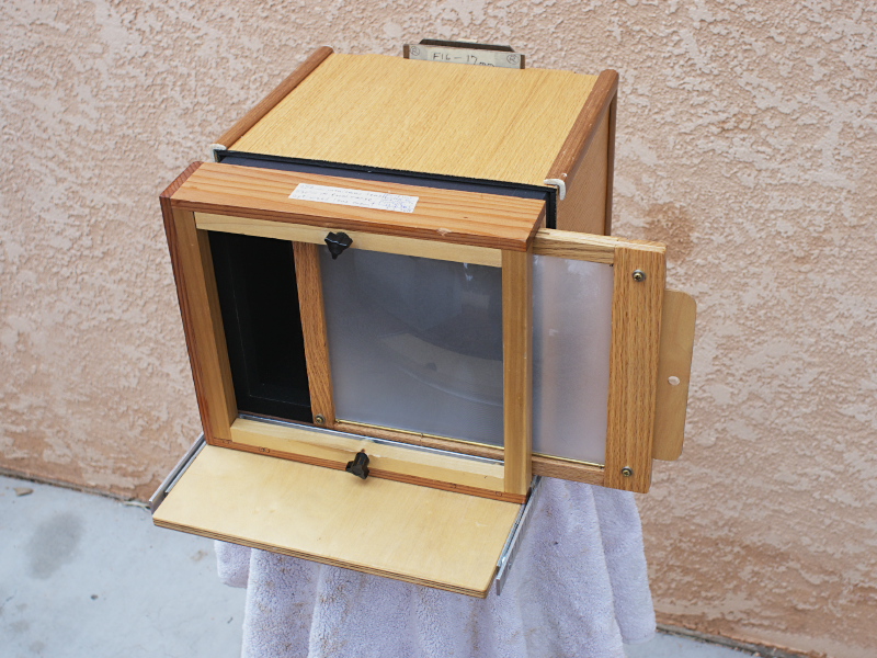
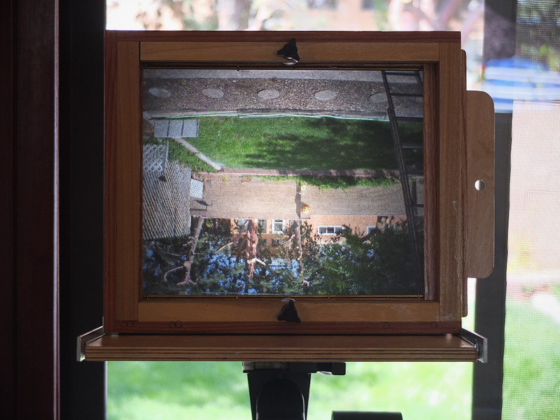
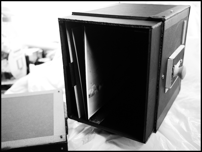
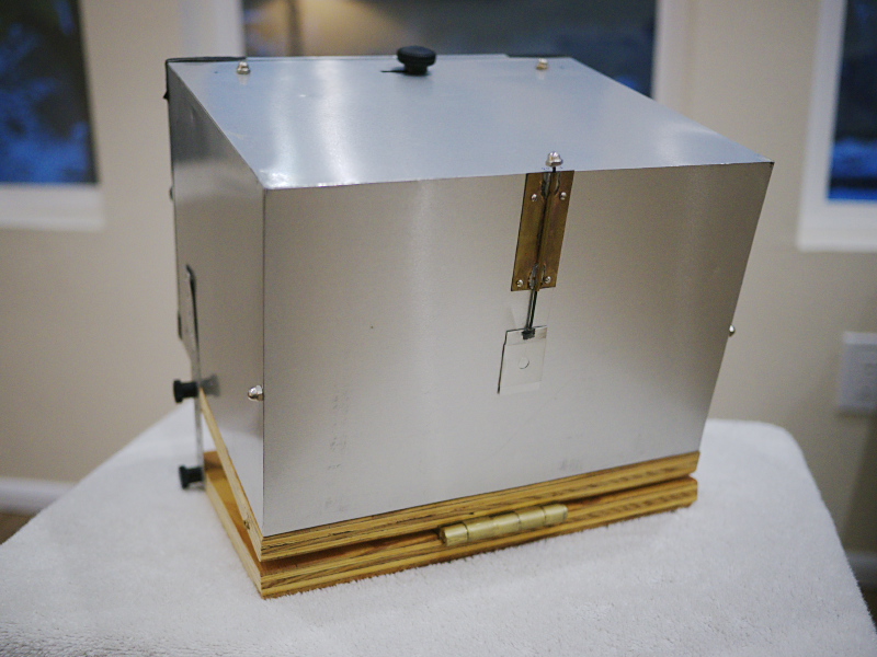
Earlier this week I created another photography video, this time about the experimental shutter I built, some years ago, for the 8" x 10" box camera.
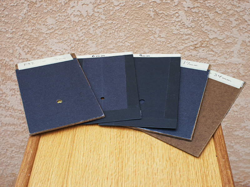
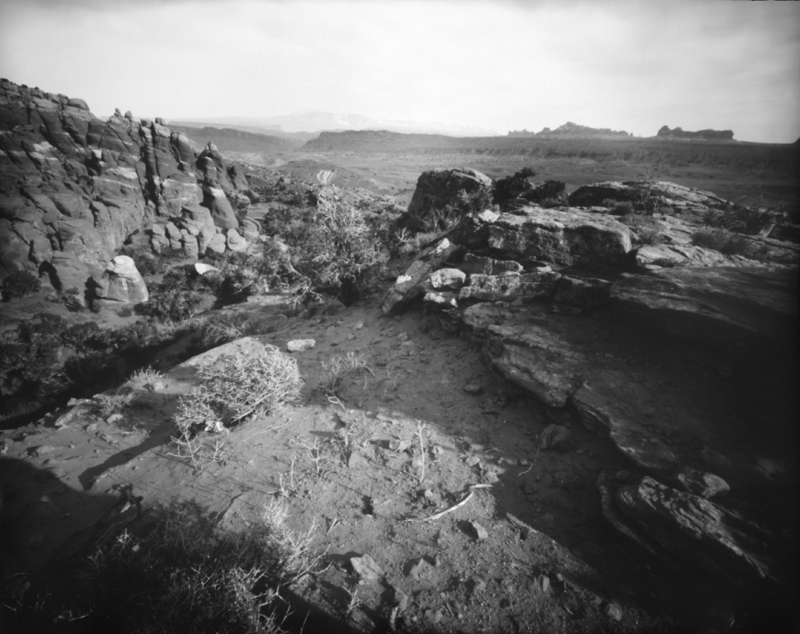
The genesis of this project was having used paper negatives in improvised lens cameras and finding that, due to the speed of the paper (I rate Freestyle Photo's Arista grade 2 RC paper at an exposure index of 12), I'd have to stop down the lens to a very small (2-3mm) aperture, in order to make the shutter speed long enough (>1 second) to accurately and repeatedly time by a hand-operated shutter, in bright daylight landscape conditions.
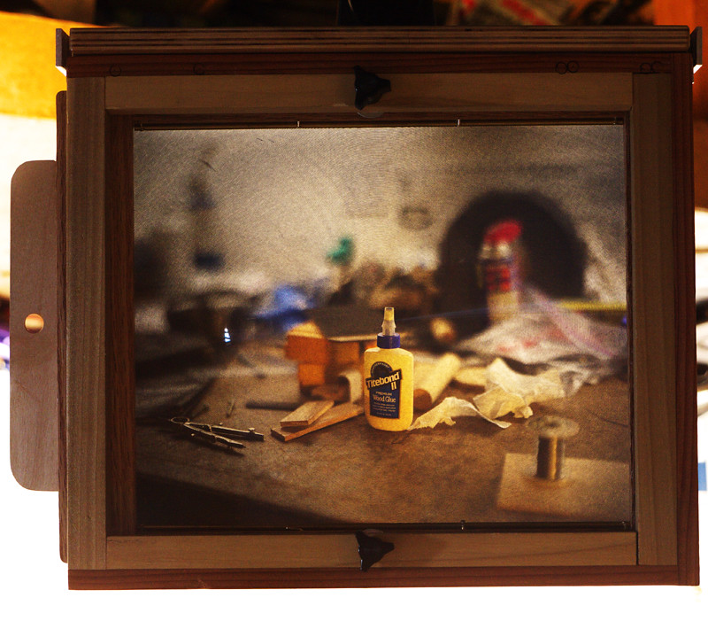
Under dimmer kinds of light, like window light, I've made a number of satisfying indoor still-life exposures in the daytime, where these improvised lenses, operating at wider apertures, display some interesting optical effects that make the resulting images rather special. But under bright daylight they have to be stopped down so much, in order for their exposures to be timed by hand, that they come to resemble hybrid pinhole/lens optics, lacking those optical aberrations I've come to appreciate from adapted optics, like binocular objectives and meniscus lenses.
So it seemed that I'd need some kind of shutter mechanism. But how?
I spent a long time cogitating about simple mechanical shutters, and ended up making a series of proof-of-concept sketches over several years, trying to find some design that might prove workable. In the end, I felt that I just had to start building something, and so it became a design-as-you-build kind of project, using scrap bits of hardware I'd collected over the years; my motto being something along the lines of never throw anything away, you might use it someday.
What I was trying for was a shutter whose speed could be varied over some practical speed range, to account for differences in exposure. Many of the early designs I considered were simple slit shutters, operated by spring tension and moving either horizontally or vertically, with the width of the slit accounting for the variation in exposure. But I soon realized that with a fixed spring tension a variable slit shutter operating up front at the lens would only yield a small range of speed variations.
After some time I realized that I could make the traveling slit camera into a rotary blade camera, and by altering the angle between the blades the timing could be adjusted. However, my initial idea was much more grand: by slowing down the speed of rotation, I could have a wider range of speeds, from multi-seconds long to fractions of a second, perfect for paper negative media.
But I never got far enough along with this design to build a practical mechanism for slowing down the rotation while making its speed reliable and repeatable. The one big idea I had for this was based on a mechanism I'd seen years earlier, while repairing a Technics audio cassette deck, which was the method used to dampen the speed of the cassette door when it was ejected. Most cassette players used a simple plastic dash-pot mechanism, a piston and cylinder, with an o-ring and some grease, so that as the spring tension tries to slam the door open, the air in the piston is released in a controlled fashion through a small opening, allowing instead the door to slowly and smoothly open. The problem with this design is when the grease hardens up over time, and the cassette door slams open uncontrollably.
Panasonic's method was different. They used a small brass whirligig, a 4-vane rotating piece that was driven to rotate by a drawstring band attached to the door mechanism. As the spring tries to forcefully slam open the door, the band rapidly spins the whirligig, the resulting air pressure slowing down and regulating the speed of the door into a smooth motion. The best part of this design was its reliability, as there were no lubricants to harden over the years.
So my idea for the shutter was to employ this whirligig mechanism, in a small but rapidly turning pulley with vanes, that the shutter cord would spin as the shutter was moving, helping to keep the speed constant. In theory, it sounds plausible; but I never got to the point of implementing it with this shutter.
As you note from the video, the problem with this shutter is that the three speed adjustments, that alter the angle between the blades, don't really offer much variation in speed; and there's too much friction in the mechanism, caused by the way I designed for compensating for light leaks.
The sad thing about this project is that it's sat dormant for some years, as I just couldn't find the motivation to get back to improving it. But now, with these You Tube videos and this blog, perhaps I've painted myself into a corner whereby now I'm forcing myself to get back and finish these projects. And that's a good thing.
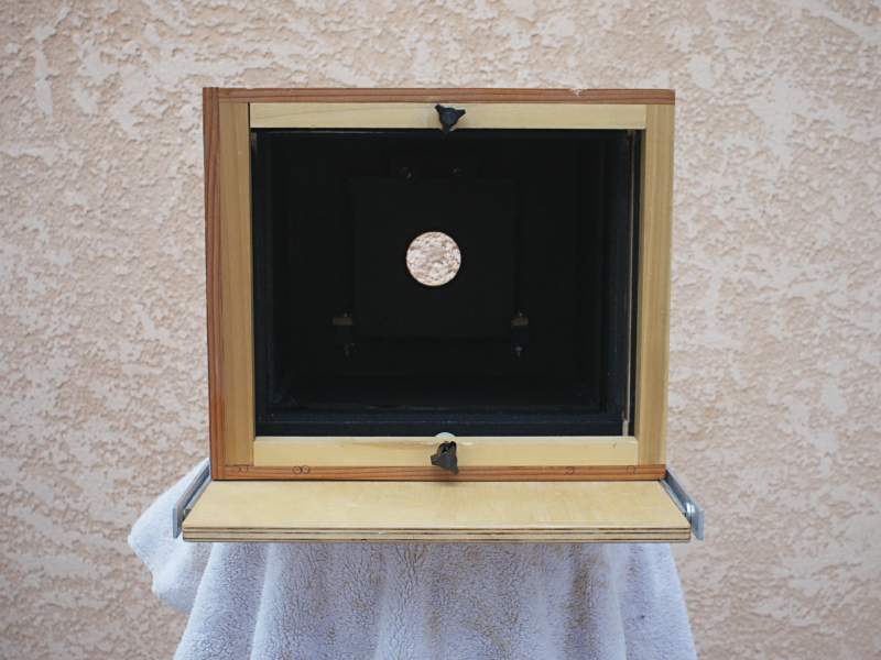
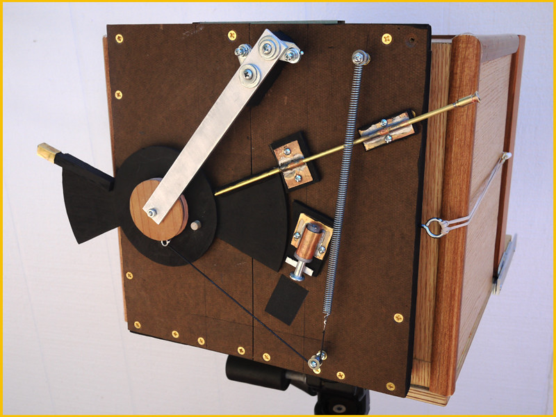
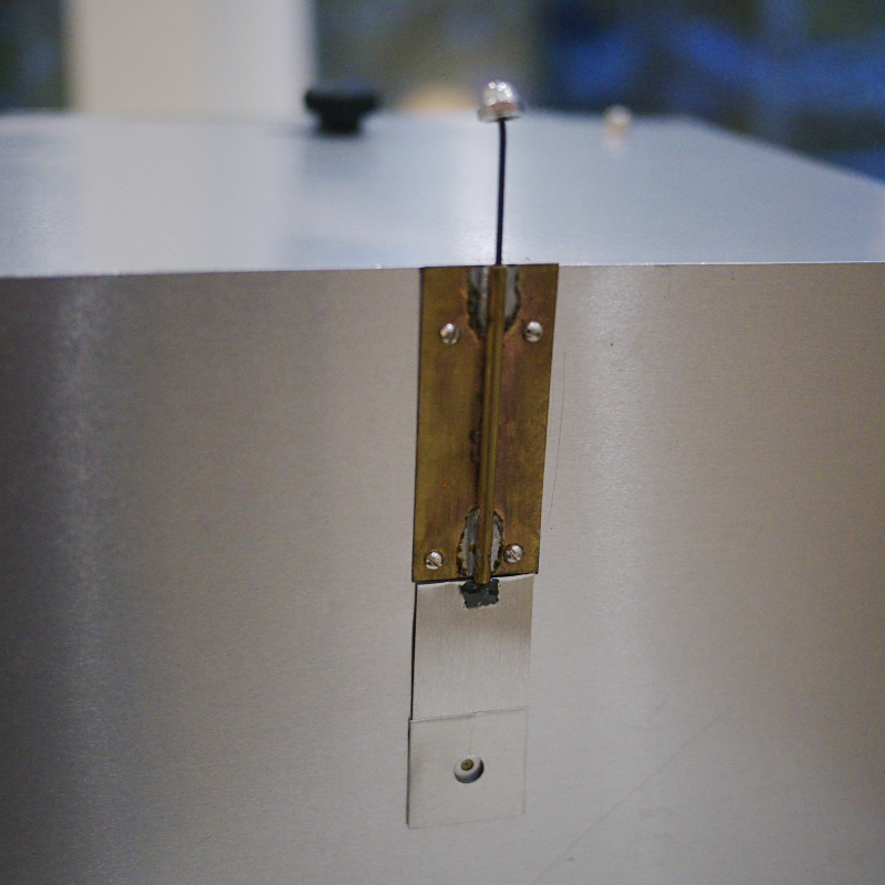
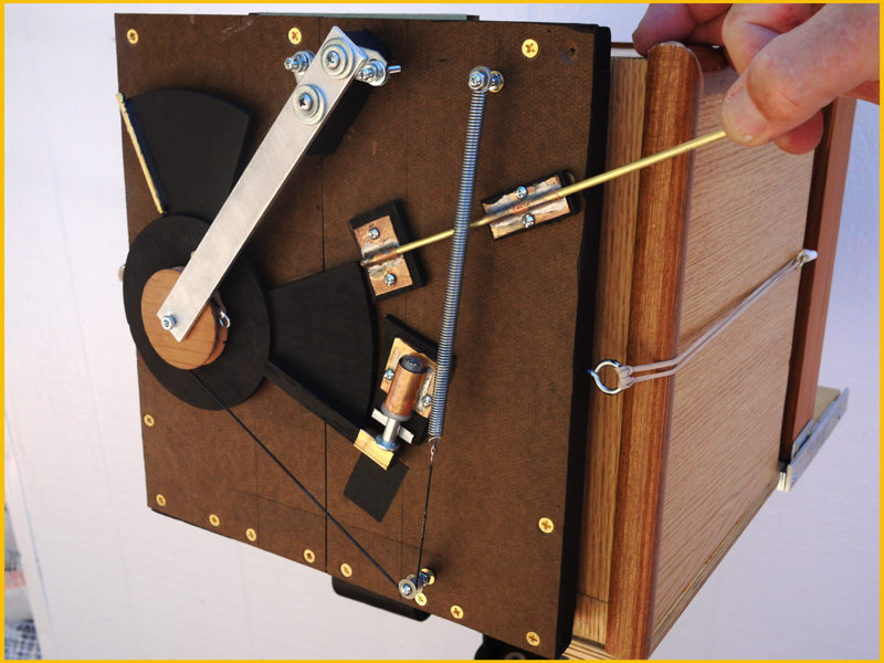
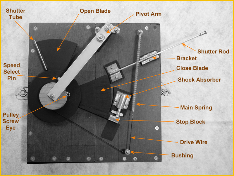
Here is a detailed photo of the shutter with the parts labelled, made a few years back; note that I've more recently changed the draw cord from a thin black to thick white cord.
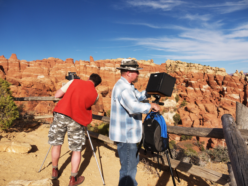
This video was the first of two parts; next week I hope to take the camera out, with shutter attached, and make some usable images. Stay tuned.